
Stereo Balance Indicator Circuit

This stereo balance meter circuit is designed to visually indicate the balance between left and right audio signals. The circuit typically employs an operational amplifier (op-amp) as the core component, denoted as U1 in the description. The op-amp is configured in a differential mode to compare the amplitude of the left (L) and right (R) audio inputs.
When the signals are equal, the output from U1 remains at a neutral voltage level, resulting in no output signal. This condition indicates perfect balance between the two channels. If a discrepancy in signal levels occurs, the output voltage from the op-amp will shift accordingly, directing the user’s attention to the channel that requires adjustment.
The circuit may also include a pair of LEDs to provide a visual representation of the balance. For instance, a green LED could indicate balanced signals, while red LEDs could illuminate when there is an imbalance, signaling the need for adjustment.
Power supply considerations are crucial for this circuit; typically, a dual supply voltage (positive and negative) is used to accommodate the op-amp's requirements. The input signals are often AC-coupled via capacitors to block any DC offset, ensuring that only the audio frequency components are processed.
Overall, this circuit serves as an essential tool for audio engineers and enthusiasts, allowing for precise adjustments in stereo sound systems, ensuring optimal listening experiences.The simplest stereo balance meter circuit schematic available on the internet! When Left and Right signals are equal, no output is present from U1 and pin.. 🔗 External reference
Related Circuits
Most of the power supply failure indicator circuits need a separate power supply for themselves. But the alarm circuit presented here needs no additional supply source. It employs an electrolytic capacitor to store adequate charge, to feed power to...
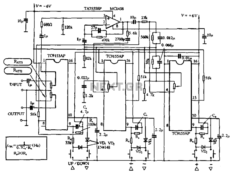
Figure 4-18 illustrates a volume potentiometer T (Xi 153AP) and a tone potentiometer T (155AP) that make up a volume and tone control circuit. This circuit includes Rx and Cx as clock oscillation elements, with values selectable based on...
The circuit of automatic emergency light presented here has the following features: 1. When the mains supply (230V AC) is available, it charges a 12V battery up to 13.5V and then the battery is disconnected from the charging section....
The circuit depicted in the figure allows for the selection of optimal operating conditions and a suitable allocation of the temperature coefficient for the resonant circuit components. The resonance occurs at both ends of the circuit. Additionally, the exchange...
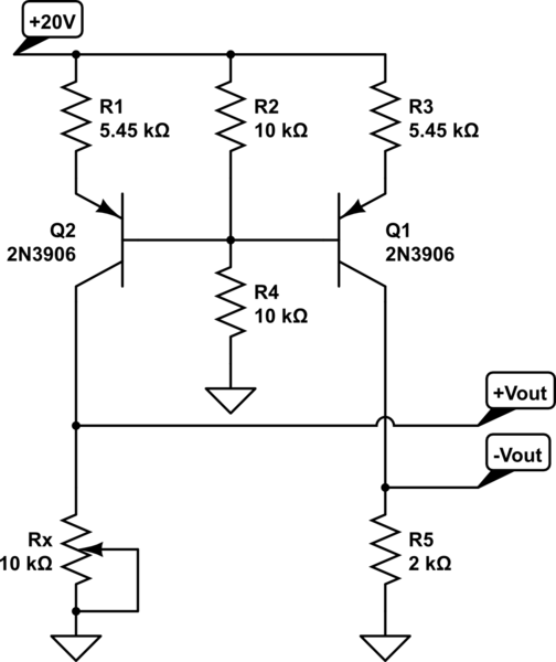
A functional circuit utilizing an operational amplifier (op-amp); however, the instructor indicated that op-amps can be challenging to work with and provided transistors as an alternative. Operational amplifiers (op-amps) are versatile components commonly used in various electronic circuits for...
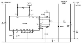
The circuit illustrates a TL494 pulse width modulated step-down converter schematic. This circuit allows for testing of line regulation, load regulation, output ripple, short circuit current, and efficiency under various input voltage conditions. A detailed table of these tests...