
mixer

The D.C. mixer circuit is designed to combine multiple direct current (DC) signals into a single output, making it particularly useful in synthesizer applications where different control voltages need to be mixed. This circuit typically employs operational amplifiers (op-amps) configured in a summing amplifier arrangement, which allows for the linear combination of input signals.
In a standard D.C. mixer, the input signals are fed into the inverting and/or non-inverting terminals of the op-amps. Resistors are used to set the gain for each input, ensuring that the output reflects the desired mix of the input voltages. The output of the mixer can then be used to control various parameters in a synthesizer, such as pitch, filter cutoff, or modulation depth.
The design may also include features such as adjustable gain for each input channel, allowing for fine-tuning of the mix according to the specific requirements of the application. Additional components like capacitors can be utilized to filter out noise, ensuring that the output signal remains clean and stable.
When implementing this circuit, careful attention must be paid to power supply requirements, as op-amps typically require a dual power supply for optimal performance. Additionally, the layout of the circuit should minimize interference and maintain signal integrity, particularly in environments with high electromagnetic interference.
Overall, the D.C. mixer serves as a fundamental building block in synthesizer design and other electronic control systems, enabling the integration of various control voltages into a cohesive output signal.Electronic project describing a D.C. Mixer for Synthesizers and other control applications.. 🔗 External reference
Related Circuits

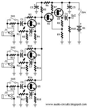
This circuit combines two or more audio channels into a single channel (for example, converting stereo to mono). It is capable of mixing multiple channels while consuming minimal power. The schematic illustrates two inputs, but additional inputs can be...
In 2011, designing a frequency converter circuit typically involves selecting an integrated circuit (IC) that meets specific requirements regarding gain and mixer spurious products, along with adding a couple of filters and a power supply. Often, the oscillator is...
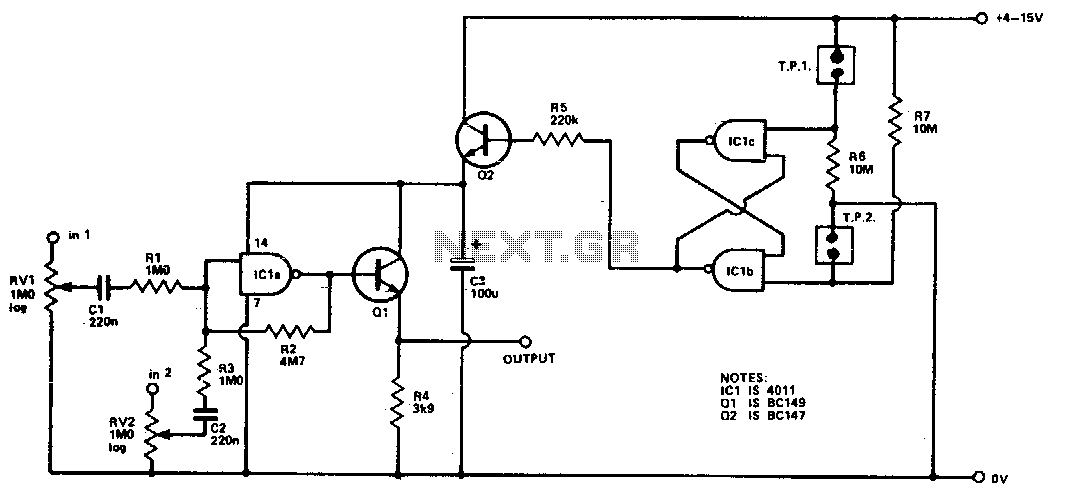
Four inputs can be mixed by duplicating the circuit to the left of C3 and using the fourth gate of ICI. Two gates are used in a touch-operated switching circuit that controls the voltage on the base of switching...
A stomp-box was designed and built for Grammy-winning resophonic guitar player Stacy Phillips. He typically uses two transducers on his Dobro-style instruments: a piezo element mounted internally and a gooseneck-mounted electret microphone positioned approximately one inch above the resonator...
The following circuit illustrates a Mini Audio Mixer with Level Control Circuits. Features include switchable high/low sensitivity, providing high performance. The Mini Audio Mixer circuit is designed to facilitate the mixing of multiple audio signals while allowing for level control...
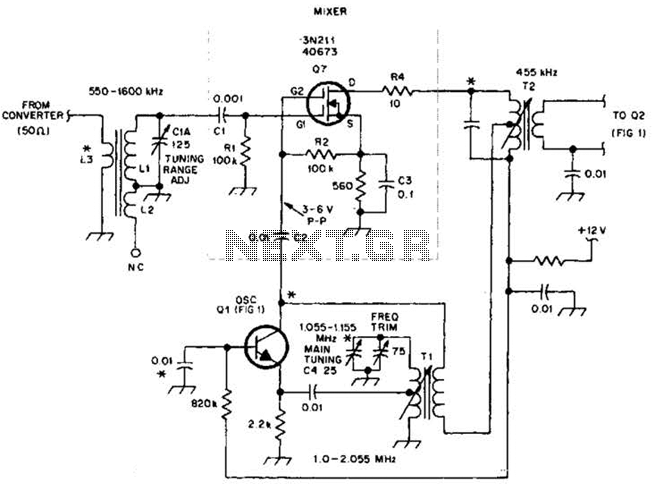
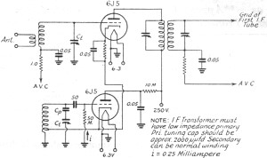
This circuit is an enhanced front end for upgrading a transistor AM receiver. This front end is beneficial when the radio is intended to function as a tunable IF amplifier with shortwave converters. The circuit described serves as a sophisticated...