
Audio AmplifierCircuit - 30 Watts

The design of a small guitar amplifier can be effectively executed by utilizing a 30 Watt amplifier circuit that operates on a single 12VDC power supply. This type of amplifier typically uses a Class AB output stage to achieve a balance between efficiency and sound quality, making it suitable for musical applications. The inclusion of a preamplifier stage is essential for adjusting the input gain and tone control, allowing for enhanced sound shaping before the signal reaches the power amplifier.
For the preamplifier, a simple transistor-based or op-amp-based circuit can be employed. The preamp should include tone control circuitry, such as a tone stack that allows for adjustments of bass, midrange, and treble frequencies. This can be achieved using capacitors and resistors arranged in a configuration that allows for the desired frequency response.
To implement a master volume control, a potentiometer can be placed in the output stage of the amplifier circuit. The master volume should be connected to the output of the power amplifier, prior to the signal being sent to the speaker. This configuration allows for overall volume adjustments without affecting the tonal characteristics set by the preamp and tone control.
It is advisable to use a logarithmic taper potentiometer for the master volume control to ensure a more natural feel when adjusting the volume. The value of the potentiometer can typically range between 10kΩ to 100kΩ, depending on the specific requirements of the amplifier circuit and the desired level of control.
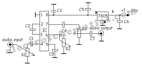
In summary, the proposed guitar amplifier design involves a 30 Watt circuit powered by a single 12VDC source, with a preamplifier stage for gain and tone adjustments, and a master volume control implemented at the output stage using a potentiometer. This configuration allows for a versatile and user-friendly amplifier suitable for various musical applications.I`m a bit of a newbie, but I love to experiment. I thought I would try to make a small guitar amplifier using some of the circuit designs posted here. I`m thinking of using this 30 Watt design (actually, the single 12VDC version mentioned in the comments below), but feed it with a preamp ( ) to be able to adjust input gain and have some tone cont
rol. Then I would like to add a master volume on the backend, but I haven`t found any circuit designs for this. Only digital volume circuits, but I`d like to use a pot. Question #2: How can I add a master volume to this amplifer circuit In the comments below, you mention adding a volume pot to the INPUT of this circuit.
That`s sort of what I`d be doing with the pre-amp. Would it be logical to place a volume pot somewhere in the OUTPUT 🔗 External reference
Related Circuits

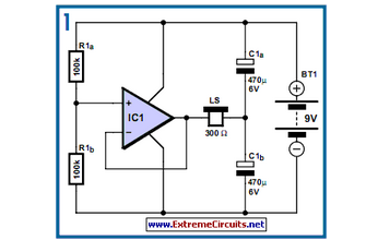
10W audio amplifier with bass boost. High quality, very simple design. No preamplifier required. Circuit diagram: Parts: P1 22K logarithmic potentiometer (dual-gang). This audio amplifier circuit is designed to deliver a power output of 10 watts, making it suitable for...
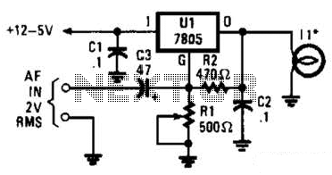
In the visible-light transmitter, a 7805 voltage regulator is configured in a variable-voltage setup, with an audio signal input to modulate the output voltage. The modulated output voltage is utilized to transmit information through an incandescent lamp. The visible-light transmitter...

The TDA8581(T) from Philips Semiconductors is a 1-watt Bridge Tied Load (BTL) audio power amplifier that can deliver 1 watt of output power into an 8-ohm load at a total harmonic distortion (THD) of 10% while using a 5V...
Both halves of the circuit are identical. Both inputs have a DC path to ground via the input 47k control, which should be a dual logarithmic type potentiometer. The balance control is a single 47k linear potentiometer, which, when...
A simple audio compressor is designed using the SSM2165 integrated circuit (IC). There is limited explanation available regarding the schematic of this compressor circuit; however, special attention should be given to the capacitor used. The audio compressor circuit utilizing the...
Designs for audio amplifiers with DC coupling to the load are not commonly seen today, despite their clear benefits. One advantage... Audio amplifiers utilizing DC coupling to the load present several notable advantages in specific applications. DC coupling allows for...