
Logic PSU with Overvoltage Protection

The circuit described is a precision voltage regulator designed to provide a stable 5V output suitable for TTL and 74LS series integrated circuits. These ICs are sensitive to voltage fluctuations, making it essential for the power supply to maintain a consistent voltage level while being resilient to transient spikes.
The heart of the circuit is a zener diode, which serves as a voltage reference. When the output voltage exceeds the zener breakdown voltage, the diode conducts, providing a rapid response to overvoltage conditions. This feature is critical for protecting sensitive ICs from damage due to voltage spikes, which can occur in various scenarios such as power surges or inductive switching.
To enhance the circuit's response time, a combination of capacitors can be employed at the output. These capacitors act as local energy reservoirs, smoothing out any rapid fluctuations in voltage and providing immediate current when needed. The selection of capacitor values should be based on the load characteristics and the expected transient response.
Additionally, the circuit can incorporate a fast-acting electronic fuse or a resettable fuse (PTC) that can respond much quicker than traditional fuses. This electronic fuse can disconnect the load in the event of a fault condition, providing an additional layer of protection for the connected ICs.
The power supply should also include filtering components, such as inductors or ferrite beads, to further suppress high-frequency noise that may affect circuit performance. Proper PCB layout and grounding techniques are vital in minimizing electromagnetic interference (EMI) and ensuring stable operation.
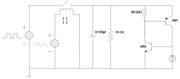
In summary, this 5V regulated power supply circuit is designed with precision and transient protection in mind, utilizing a zener diode for voltage regulation, capacitors for transient response, and additional protective components to safeguard sensitive TTL and 74LS series integrated circuits from potential damage.The 5 volt regulated power supply for TTL and 74LS series integrated circuits, has to be very precise and tolerant of voltage transients. These IC`s are easily damaged by short voltage spikes. A fuse will blow when its current rating is exceeded, but requires several hundred milliseconds to respond.
This circuit will react in a few microseconds, triggered when the output voltage exceeds the limit of the zener diode. 🔗 External reference
Related Circuits
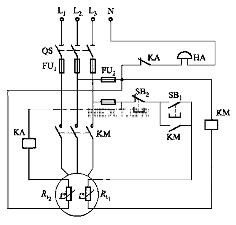
The circuit illustrated in Figure 4-2 employs two thermal resistors. One, designated as Rc, functions as overload protection, while the other, labeled Rt, serves as an alarm. The circuit in question integrates two thermal resistors to monitor temperature changes and...
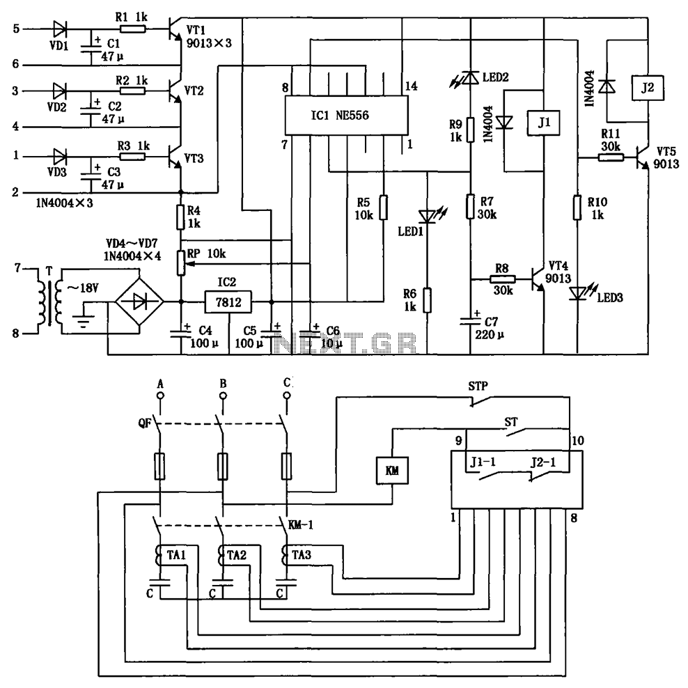
The circuit depicted is utilized in a power supply system to promptly disconnect the power supply in the event of an over-voltage condition during either the grid's on or off phase, thereby protecting the power capacitors. This circuit serves a...

The circuit presented utilizes NAND logic gates from the Hitachi HD series, specifically the HD74LS00, which is a quad NAND integrated circuit. A special technique has been implemented to achieve three-state operation using a single IC. Gate N1 is...
A series of current pulses are applied to the simulated structure, and average currents of the 70% to 90% section of each curve are calculated. Voltage versus time curves are obtained from the simulation, and the average voltage of...
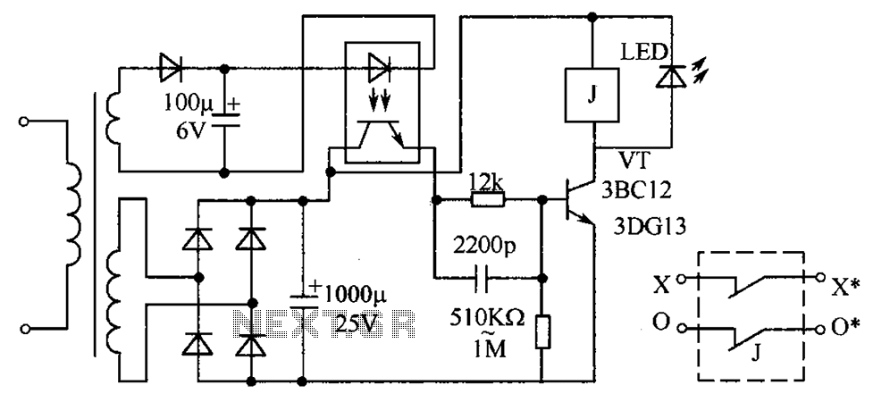
The circuit protection mechanism utilizes optocouplers for on-off control. Under normal voltage conditions, the output from the optocouplers is minimal, and the VT transistor operates in reverse bias. However, if the circuit voltage increases due to reasons such as...
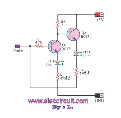
This logic probe circuit is designed for checking voltage levels in TTL circuits. It receives signals from the circuit being tested and indicates whether the logic level is high or low. When the input voltage at the probe tip...