
4-Decade Square-Wave Generator

The circuit is designed to produce a square wave output, which is essential for various applications such as signal testing, waveform generation, and clock pulses in digital circuits. The operational amplifier operates in a feedback loop configuration, allowing it to oscillate and produce the desired frequency output. The relaxation oscillator relies on the charging and discharging of capacitors, which are not explicitly mentioned but are typically integral to such designs.
The calibration controls, R1 to R4, allow for fine-tuning of the frequency ranges, ensuring precise adjustments can be made based on application needs. The frequency selection switches S1-a and S1-b facilitate easy user interaction, enabling quick changes to the desired frequency range without the need for complex adjustments.
Output level adjustment through R10 is crucial for applications requiring specific voltage levels, ensuring compatibility with downstream circuitry. The output characteristics of approximately 15 V peak-to-peak are suitable for driving various loads or for interfacing with other electronic components.
In summary, this circuit provides a versatile solution for generating square wave signals across a wide frequency range, with user-friendly calibration and output level adjustment features, making it suitable for a variety of electronic applications. This circuit will generate a square wave of 2 Hz to 20 kHz. The circuit uses an op amp in a relaxation-oscil lator configuration. The output is about 15 Vpp. Rl through R4 are calibration controls for each of the four frequency ranges, as selected by SI-a and Sl-b. RIO adjusts the output level. S1 Frequency 1= 2Hz - 20Hz 2= 20Hz-200Hz 3= 200Hz - 2kHz 4= 2kHz-20kHz
Related Circuits
This is a simple function generator built around a single 8038 waveform generator IC. The circuit is capable of producing sine, square, or triangle waves within a frequency range of 20Hz to 200kHz. The function generator circuit utilizes the 8038...
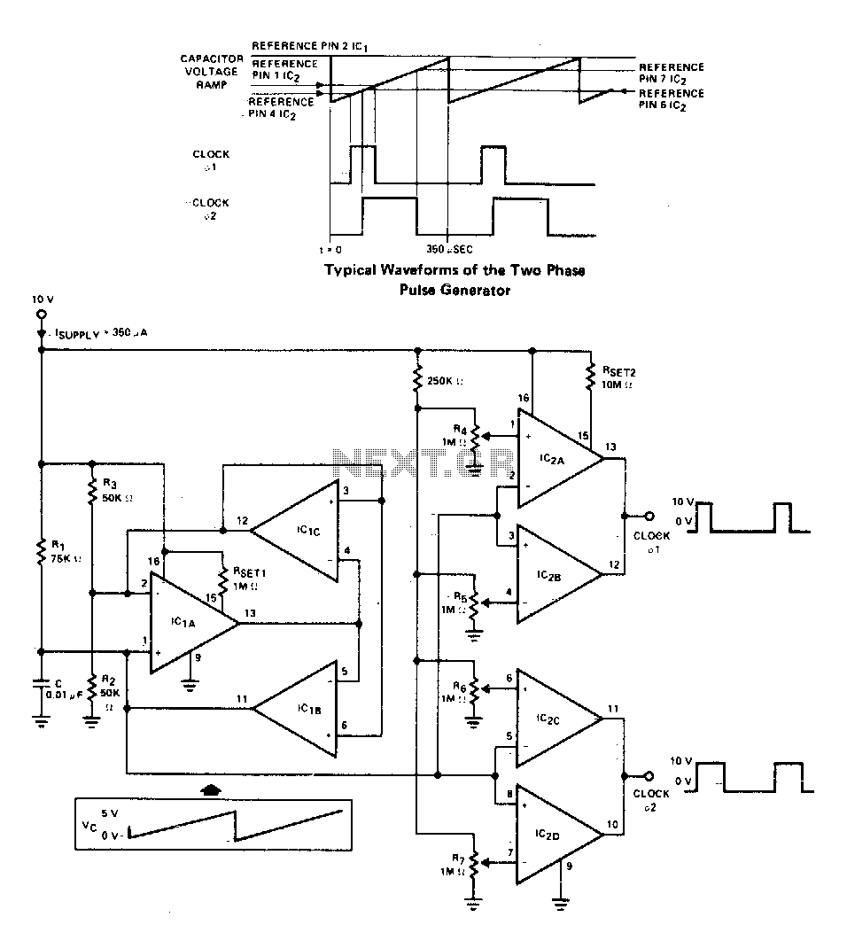
A two-phase clock generator utilizes two L161 integrated circuits to produce pulses with adjustable widths and phase relationships. Additionally, a ramp generator supplies input to two variable window comparators, which are configured using IC2A-IC2B and IC2C-IC2D, respectively. The two-phase clock...
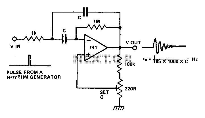
The circuit is a multiple feedback bandpass filter. A brief click (pulse) causes it to resonate at its natural frequency. The oscillations diminish exponentially, closely resembling various naturally occurring percussive or plucked sounds. The higher the quality factor (Q),...
The first positive pulse from a classic 555-based oscillator is always 1.6 times longer than the subsequent pulses. This discrepancy arises because, during the initial cycle, capacitor C2 begins charging from 0 V. While this is typically not an...
This is a circuit that generates white noise, rolled-off to drive earphones or a small speaker. White noise creates is a "rushing" sound, which sounds something like air rushing by your ear(s). White noise would be flat with frequency,...
The tone generator was a straightforward project developed as a test unit for a customer design job. It utilizes two analog switches controlled by microprocessor code: one switch manages the signal directed to the operational amplifier that drives the...