
tone generator circuit

The tone generator circuit is designed for efficiency and simplicity, making it suitable for testing various audio signals in a client’s application. The circuit comprises a microcontroller that outputs control signals to two analog switches, typically implemented using CMOS technology for low power consumption and high switching speed.
The first analog switch is responsible for directing the audio signal to an operational amplifier (op-amp). The op-amp is configured in a non-inverting amplifier configuration to boost the signal level to a suitable output range. The gain of the op-amp can be adjusted by selecting appropriate resistor values in the feedback loop, allowing for flexibility based on the specific requirements of the test signals.
The second analog switch is crucial for signal routing from the tone detector, which is integrated into the client’s board. The tone detector identifies specific frequency tones and generates a corresponding output signal. The analog switch then channels this output to the appropriate LEDs, providing visual feedback regarding the detected tones. This feedback mechanism is essential for the testing process, allowing operators to quickly ascertain whether the tone detection circuit is functioning correctly.
The design's low parts count contributes to its reliability and cost-effectiveness, making it an attractive solution for testing applications. The use of a microcontroller simplifies the control logic and allows for easy reprogramming, enabling the unit to adapt to various testing scenarios without significant hardware changes. Overall, this tone generator exemplifies an effective approach to creating a test unit that meets the needs of specific customer requirements while maintaining a compact and efficient design.The Tone generator was a simple project built as a test unit for a customer design job. We use two analog switches controlled by the microprocessor code - one switch controls the signal going to the op-amp that drives the output, the other switch actually steers the results from the tone detector (the item on the clients board that is being tested ) to light the appropriate LEDs. This unit worked quite well, considering the low parts count. 🔗 External reference
Related Circuits
Observing my Boss pedals and how they were switched on and off I figured there must be more to it. It took me only about 4 hours to design and test this circuit. It works very well and I’m...
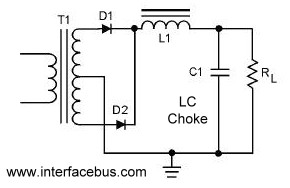
A circuit that utilizes both positive and negative alternations in an alternating current to generate direct current. There are two types of full-wave rectifier circuits: one that employs two diodes and requires a center-tapped transformer, and another that uses...
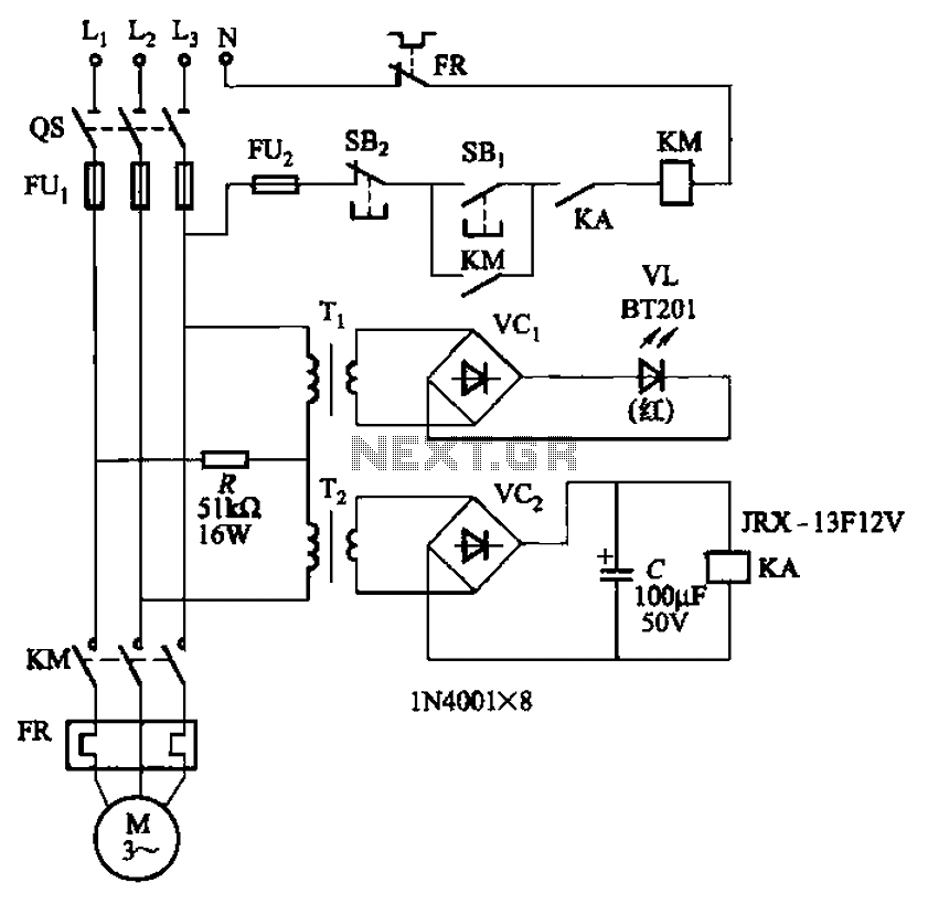
The circuit depicted in Figure 3-92 employs a dual-phase sequence protection relay for sensing. When the power supply exhibits a positive phase sequence (U, V, W), the relay KA is activated. If the power supply maintains the correct phase...
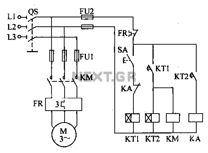
After the power switch is activated, the motor does not start immediately but instead has a specified delay period. This setup allows the machine to perform automatic intermittent lubrication control. The circuit for the motor boot delay and intermittent...
As with any audio mixer circuit, a slight loss is always introduced. The final summing amplifier has a gain of 2 or 6dB to overcome this. The input line level should be around 200mV RMS. The mic inputs are...
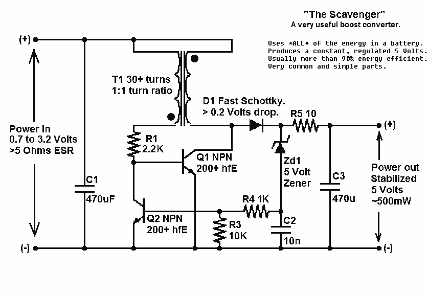
Presented here is a significant advancement in the design of simple, cost-effective, and efficient boost converters. To achieve an effective design, it is essential to convert current to voltage as efficiently as possible. This circuit excels in this regard. The...