
Audio Oscillators

The operation of oscillators is fundamentally rooted in the concept of positive feedback, which ensures that the output signal reinforces the input signal. In the case of the R-C phase shift oscillator, the circuit typically consists of an inverting amplifier followed by a phase-shift network. The phase-shift network is composed of three identical R-C sections, which collectively provide a total phase shift of 180° at the desired frequency. The selection of resistor and capacitor values is critical; they must be chosen to ensure that the phase shift aligns with the frequency of oscillation.
The Wien bridge oscillator, another notable R-C oscillator, employs a bridge circuit that balances two arms of resistors and capacitors, allowing for precise frequency control. This oscillator is known for its stability and low distortion, making it suitable for audio applications. The feedback mechanism in this oscillator utilizes a combination of resistive and capacitive elements to achieve the necessary phase shift while maintaining a stable amplitude.
In both types of oscillators, careful consideration of component values and configurations is essential to achieve the desired performance. The stability of the oscillation frequency, as well as the amplitude of the output waveform, can be influenced by the quality of the components used and the overall design of the circuit. These factors contribute to the effectiveness of R-C oscillators in generating audio frequencies in various applications, including signal generators, tone generators, and audio processing equipment.So far, we have considered the oscillators which use L-C tuned circuit that causes a phase shift of 180 ° due to inductive or capacitive coupling in addition to a 180 ° phase shift produced by the transistor itself. The oscillators employing L-C elements, called the L-C oscillators, are very popular for generating high frequency oscillations but t
hey cannot be employed for generation of low frequency oscillations as they become too bulky and expensive. R- C oscil lators are commonly used for generating audio-frequencies as they provide good frequency stability and waveform.
Also, with the advent of IC technology, R-C network is the only feasible solution, as it is very difficult to make a too high value inductance in an integrated circuit. Two com monly used R-C oscillators are (i) R-C phase shift oscillator and (ii) Wien bridge oscillator.
Another commonly used audio-oscillator is the beat frequency oscillator (BFO). So these three audio-oscillators will be discussed here. For producing oscillations in an oscillator circuit we need positive feedback which means that the voltage signal feedback should be in phase with the input signal. For providing a positive feedback at one particular frequency, an inverting amplifier may be used with a feedback network that causes a phase shift of 180 ° at the desired frequency of oscillation, as shown in fig.
(a). The 180 ° phase shift in the feedback signal can be obtained by a suitable network consisting of three R-C sections, as shown in fig. (b). When a phase-shift network such as that indicated in fig. is used in a phase shift oscillator, the R`s and C`s must be selected so as to produce a phase shift of 180 ° at the desired frequency of oscillation.
The output of the voltage amplifier is fed to the input to the phase-shift network. Thus V1 = Vout. The output resistance of the amplifier is designed to be very small in comparison to the input impedance of the phase-shift network. The output voltage of the phase-shift network, V2 is fed into the input of the amplifier i. e. , V2 = Vin. The amplifier`s input impedance must be much larger than the output impedance of the phase-shift network.
Alternatively, a positive feedback can be obtained by using two stages of amplifiers each giving a phase shift of 180 °. A part of this output is fedback to the input through a feedback network without causing any further phase shift.
Wien bridge oscillator operates on this principle. 🔗 External reference
Related Circuits
The goals were achieved by utilizing a discrete-components operational amplifier (op-amp) driving a complementary common-emitter output stage configured for Class B operation. In this configuration, for small output currents, the output transistors remain off, allowing the op-amp to supply...
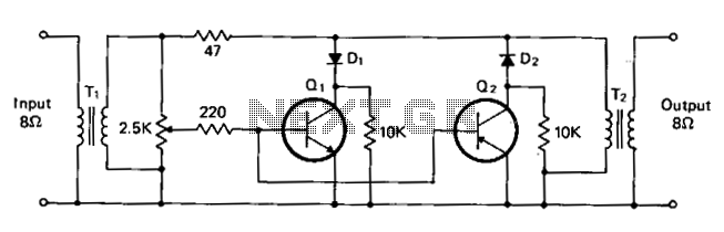
T1 and T2 are 600 to 8-ohm transformers (any transistor radio output transformers with 500 to 4-ohm impedance may be used). Q1 is a 2N2222 NPN transistor, and Q2 is a 2N2907 PNP transistor. D1 and D2 are 1N270...
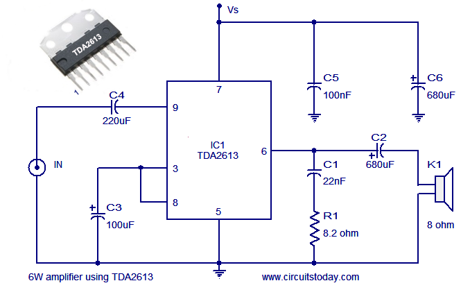
A simple and easy-to-build Hi-Fi audio power amplifier circuit is presented here. This 6-watt Hi-Fi audio amplifier circuit utilizes the TDA2613 integrated circuit (IC). The circuit design employs the TDA2613, which is a high-performance audio amplifier IC known for its efficiency...
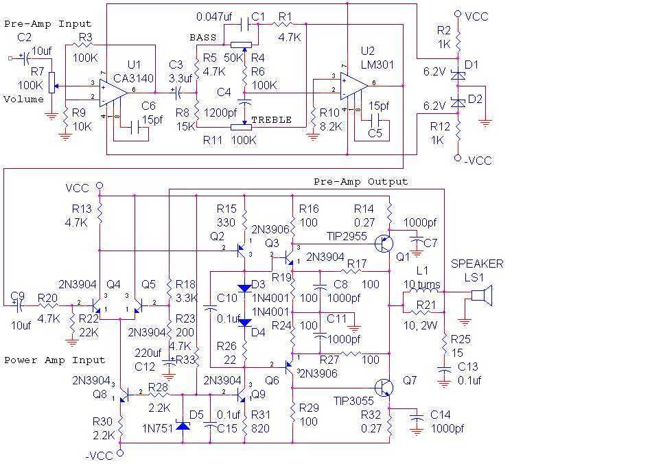
The audio amplifier shown below provides 14 watts of power, but can provide much more simply by increasing the power supply voltage. This amp was built in 1975 and has worked reliably ever since. The power amp portion was...

This is a standard amplifier based on LM 1875. It can deliver 20 W, with an 8 Ω speaker and 60V power supply even 30 W. The capacitors C4 and C5 should preferably be as close to the IC down....
After experimenting with a stereo version of the VU meter described in a previous blog post, a studio-grade VU meter is now being presented. This meter features 24 steps, spaced equally every 3 dB, and covers a wide dynamic...