
4 time ON-OFF relay circuit

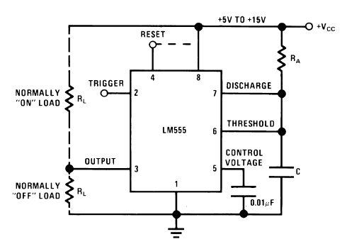
The circuit design consists of a timer integrated with a relay to control the switching operation. The primary components include a timer IC, such as the 555 timer, configured in monostable mode, a relay suitable for the load, and supporting passive components like resistors and capacitors.
Upon the application of power, the timer IC is activated, initiating a timing cycle based on the resistor-capacitor (RC) network connected to its timing pins. The output of the timer remains low during the timing period, ensuring that the relay remains deactivated. The relay's coil is connected to the output of the timer, which is typically at a low state during the timing interval.
Once the timer completes its designated timing period, the output transitions to a high state, energizing the relay coil. This action closes the relay contacts, allowing current to flow through the load connected to the relay. The relay will remain activated until power is removed from the circuit or the timer is reset.
To ensure stability and prevent false triggering, it is advisable to include a debounce circuit if the timer is being activated by a switch. Additionally, protection diodes should be placed across the relay coil to prevent back EMF from damaging the timer IC when the relay is de-energized.
Overall, the circuit provides a simple yet effective solution for timed relay activation, suitable for various applications requiring delayed switching.guys i need a 2 circuit the one is when power applied the timer will trigger and the relay will remain off when the timer runs out the relay will turn .. 🔗 External reference
Related Circuits
The kit employs an off-the-shelf microcontroller based on the AtMega328P-PU Arduino, along with a simplified version designed for ease of replication and modification by collaborators and students. This initiative aims to enable the fabrication of simplified microcontrollers for DIY...
A small electronic switch connects a battery to equipment for a specific duration when a push-button is momentarily pressed. The circuit also considers ambient light levels; when it is dark, the display cannot be read, so it is logical...
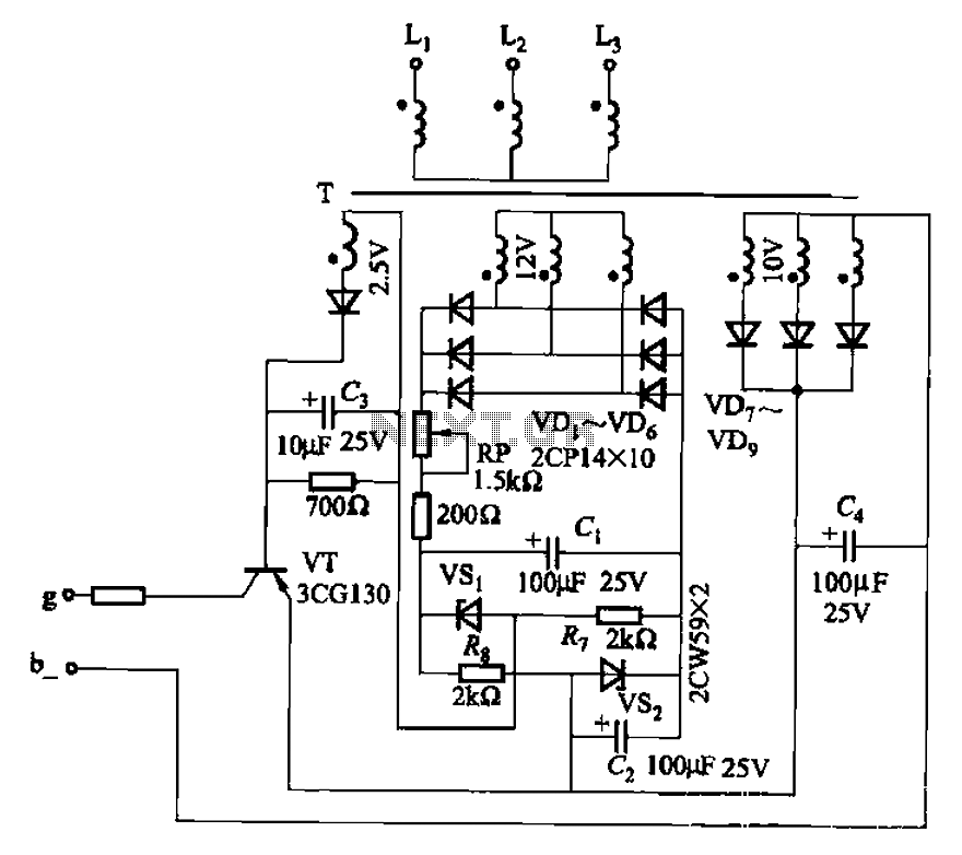
The CJ-12 Excitation Regulator is designed for automatic excitation control of small generators with a capacity of 250 kW or less. Its circuit is illustrated in Figure 7-45. The adjustment potentiometer RP allows for the modification of the measuring...
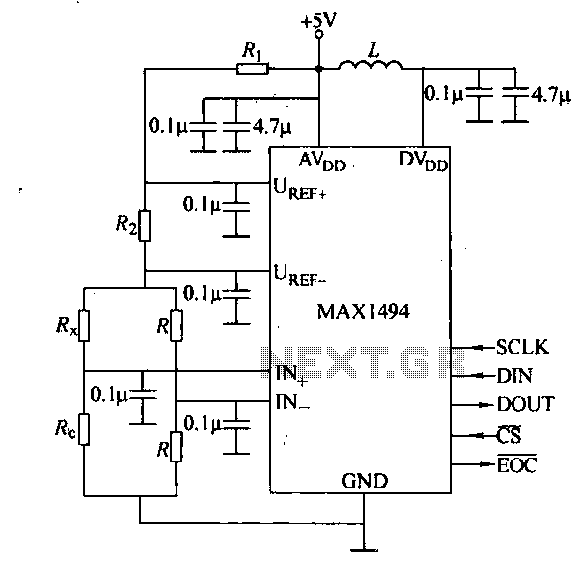
The circuit consists of the MAX1494 digital strain gauge, as illustrated in Figure 5-31. It includes a bridge formed by resistance strain gauges and a temperature compensation sheet. The standard quasi-resistance values Rl and R are incorporated into the...
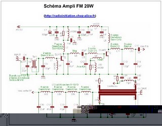
The following circuit illustrates an RF amplifier designed for FM frequencies ranging from 88 to 108 MHz with a broadband configuration. This circuit utilizes the BLV10 transistor. The RF amplifier circuit operates within the FM broadcast band, which is crucial...
The old 555 timer will work based on the specifications provided, and it is a suitable choice if this is the exact problem to be addressed. As mentioned by Steven, this type of timing block is generally referred to...