
Digital circuit strain with MAX1494

The MAX1494 is a highly integrated digital strain gauge interface designed to measure strain by using a bridge configuration of resistive strain gauges. The strain gauges convert mechanical deformation into a change in resistance, which is then translated into a voltage signal. The internal reference voltage provided by the MAX1494 is critical for ensuring accurate measurements, as it stabilizes the voltage across the bridge and allows for precise differential measurements.
In this circuit, the bridge is typically formed by four strain gauges arranged in a Wheatstone bridge configuration. This arrangement allows for the detection of small changes in resistance due to strain, enhancing sensitivity and accuracy. The temperature compensation sheet is essential for minimizing the effects of temperature variations on the strain gauge readings, ensuring that the measurements reflect only the mechanical strain.
The output voltage of the bridge, which varies between 200 mV and 2 V, is fed into the differential input of the MAX1494. This voltage range is suitable for various applications, including structural health monitoring, load cells, and pressure sensors. The MAX1494's internal circuitry amplifies and digitizes the analog signal from the strain bridge, providing a digital output that can be easily interfaced with microcontrollers or other digital systems for further processing and analysis.
In summary, the circuit utilizing the MAX1494 digital strain gauge is a robust solution for measuring strain with high precision, leveraging the advantages of a bridge configuration, temperature compensation, and digital signal processing capabilities.Circuit constituted by the MAX1494 digital strain gauge shown in Figure 5-31. See the bridge by the resistance strain gages, temperature compensation sheet R, standard quasi resistance Rl and R l trespassing into. Bridge voltage provided by the MAX1494's internal reference voltage, MAX1494 differential input termination strain bridge output voltage, the voltage range of soil 200mV- 2V.
Related Circuits
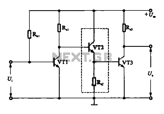
A DC-coupled multi-stage amplifier circuit consists of multiple stages of amplification using a DC-coupled configuration. Each stage utilizes NPN-type transistors, which are designed to maintain appropriate operating points at the base of each stage. As the signal progresses through...
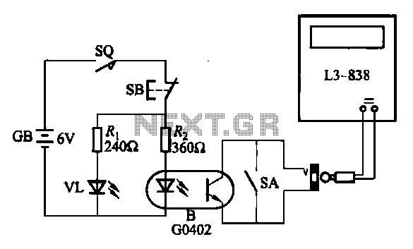
An electronic calculator features an automatic counting interface circuit, as illustrated in the accompanying figures. Figure (a) depicts a stroke switch controlled via optocoupler B. Figure (b) shows the application of a reed switch (KR) for pulse control signals....
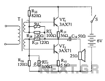
The following diagram illustrates a common output transformerless (OTL) amplifier circuit that delivers an output power of 100 mW. The circuit includes an output transformer and a capacitor, which work in conjunction with speaker units. The frequency characteristics of...
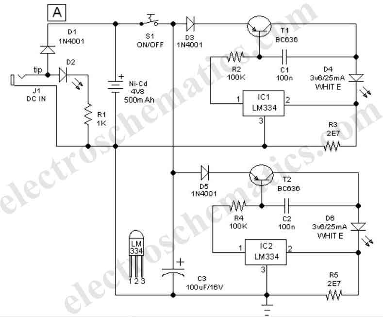
This easy-to-construct handy pen torch electronic circuit has a low component count and utilizes two power white LEDs for illumination. A low voltage (4.8V DC) supply is derived from a built-in rechargeable Ni-Cd battery pack and is converted into...
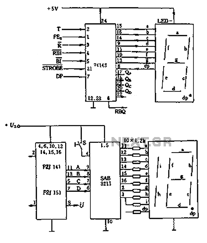
The decimal seven-segment storage decoding drive unit 74HC143 provides a constant output for all segments, each at a voltage of 5V and a current ranging from approximately 15mA to 22mA. The BCD data for the seven-segment decoder can be...

The schematic for this tutorial is illustrated below and includes all necessary components for the tutorial to function. The PIC programming circuitry is not included, as it is assumed that the PIC is either programmed externally or that the...