
Hum Circuit

The electronic schematic associated with this project involves a microcontroller circuit based on the AtMega328P-PU, which serves as the central processing unit. This microcontroller is capable of executing various tasks essential for synthetic biology applications, including data acquisition, processing, and control of peripheral devices. The circuit typically includes essential components such as a crystal oscillator for clock generation, decoupling capacitors for voltage stability, and a reset circuit to ensure reliable operation.
The simplified version of the microcontroller is designed to reduce complexity while maintaining functionality. It may feature fewer input/output pins, simplified programming interfaces, and a reduced power consumption profile, making it accessible for educational purposes. The design encourages experimentation and modification, allowing students to gain hands-on experience with microcontroller programming and circuit design.
Incorporating BioBricks into the educational framework provides a unique opportunity to draw parallels between biological components and electronic systems. Each BioBrick can be viewed as a modular unit, akin to a hardware component in a microcontroller circuit, which can be combined and reconfigured to create new functionalities. This analogy not only fosters a deeper understanding of both fields but also encourages interdisciplinary collaboration among students and researchers.
Overall, the project aims to bridge the gap between electronics and synthetic biology, empowering the next generation of innovators to explore the potential of integrating these disciplines through practical, hands-on learning experiences.Although our kit utilizes an off-the-shelf microcontroller (AtMega328P-PU based Arduino), we additionally designed a simplified version. This allows other collaborators and students to potentially replicate, or modify the project and eventually fabricate their own simplified microcontrollers for use in DIY synthetic biology education.
In many senses, the BioBricks being developed through the iGEM foundation essentially function like minute microcontroller systems. It is thus important to identify this similarity, and provide students and future researchers with an opportunity to explore it.
🔗 External reference
Related Circuits
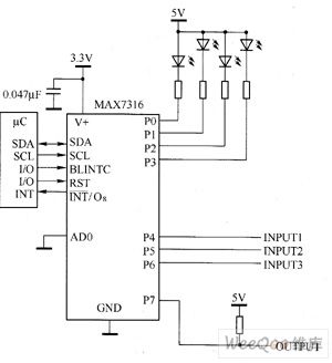
The main technical characteristics of the MAX7316 include a 400 kbps, 2-wire serial interface with a voltage tolerance of 5.5V. The operating voltage ranges from 2V to 3.6V. It features 8-bit PWM control for white LED brightness, with global...

This circuit describes the sensing of air flow using the PIC16C781 microcontroller. It utilizes Programmable Switch Mode Controllers (PSMC) that combine an Integrated Operational Amplifier, a Digital-to-Analog Converter (DAC), and a gated timer to create a thermally operated air...
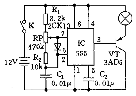
The circuit illustrated in the figure is a dimmer using the 555 timer as the core component. The 555 timer, along with resistors R1, RP, R2, and capacitor C1, forms an astable multivibrator. The oscillation frequency, f, is calculated...
This weblog focuses on electronic circuit schematics, PCB design, DIY kits, and diagrams for various electronic projects. It features a mixer that demonstrates how to create microphone pre-amplifiers suitable for both low and high impedance microphones. The design utilizes...
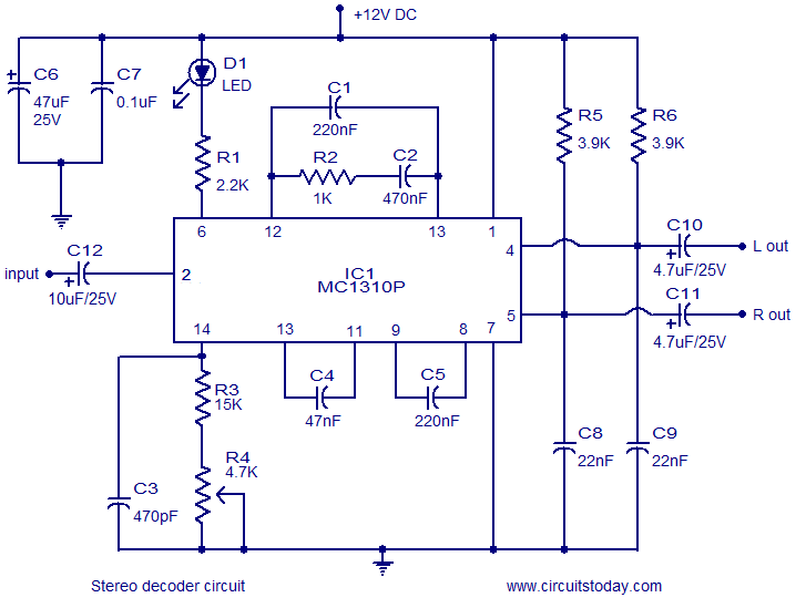
A simple FM stereo decoder circuit utilizing the MC1310P integrated circuit (IC). It operates at 12V and provides a channel separation of 40dB, making it suitable for stereo FM receivers. The FM stereo decoder circuit based on the MC1310P IC...
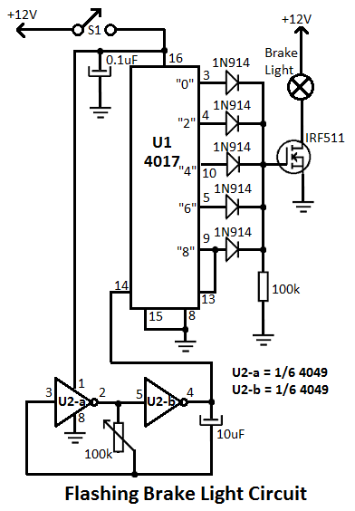
This flashing brake light circuit is designed for motorcycles. When the brake light switch S1 is closed, power is supplied to U1 and U2. The circuit utilizes two inverters from U2. The flashing brake light circuit operates by utilizing a...