
4-wire resistive touch screen interface circuit with ADS7846

The 4-wire resistive touch screen operates by detecting pressure applied to the screen's surface. It consists of two conductive layers separated by a thin insulating layer. When pressure is applied, these layers make contact, creating a voltage divider that varies based on the location of the touch. The ADS7846 interface circuit plays a crucial role in this process by converting the analog voltages generated at the touch points into digital values that can be interpreted by a microcontroller or other processing unit.
The ADS7846 chip features an integrated analog-to-digital converter (ADC) capable of handling the signals from the touch screen. It employs a successive approximation method, which allows for rapid and accurate conversion of the analog signal to a digital output. The chip also includes electronic switches that facilitate the selection of the X or Y channels based on the touch location, ensuring that the correct voltage levels are sampled.
In operation, the touch screen is connected to the ADS7846 through four main wires: two for the X-axis and two for the Y-axis. The X+ and X- terminals are responsible for the horizontal axis, while the Y+ and Y- terminals handle the vertical axis. When a user touches the screen, the voltage is read from the corresponding terminal, and the ADS7846 processes this voltage to determine the precise coordinates of the touch event.
The output from the ADS7846 is typically in the form of digital coordinates (X, Y), which can be utilized by various applications, including user interfaces and graphical displays. The linearity of the output values ensures that the touch response is accurate, thereby enhancing the user experience. Overall, the combination of the resistive touch screen and the ADS7846 interface circuit provides an effective solution for touch-based input in electronic devices.4-wire resistive touch screen. ADS7846 interface circuit. ADS7846 analog chip contains electronic switches and successive approximation A / D converter. Switched by the analog switch chip, the X + (or Y +) positive supply termination ( ), x- (or Yr) grounded (CND), the Y + (or X +) terminal and Y- (or X- ) terminal to the difference in the form of movable receiving a / D converter input. Pen contacts the touch screen at different locations, by Y + (or X +) terminal input to the on-chip A / D converter different voltage values within the input voltage through the chip A / D conversion after the stroke to give Y points (or x) output value, and the output value of the stroke position is approximately linear.
Therefore, ADS7846 output value of X and Y (ie coordinates) will be able to describe the strokes on the touch screen point of location.
Related Circuits
This device is a combination digital clock timer and solar panel charge controller designed to maintain a deep cycle battery charged by a solar panel. The timer output controls a 12-volt load for a 32-minute interval each day. The...
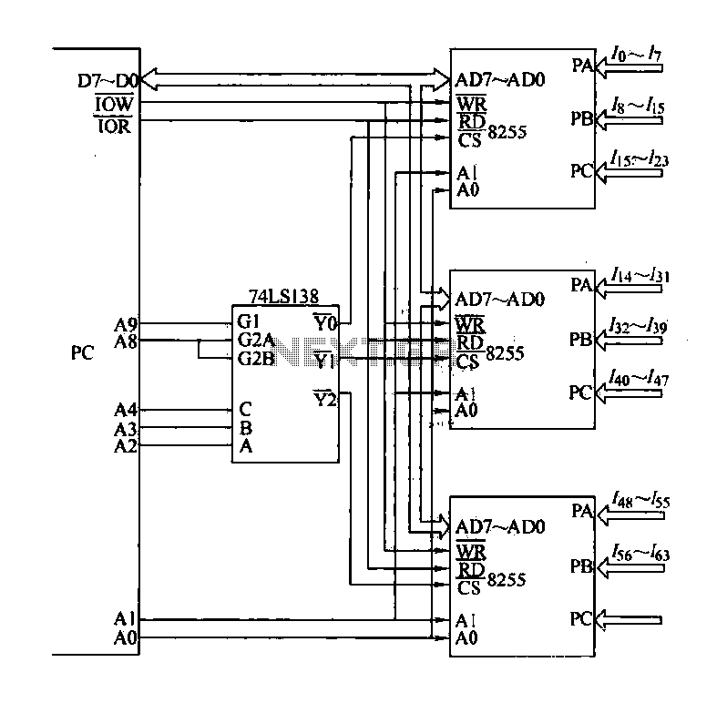
The computer control system is designed to detect signal path switching, requiring multiple input interface expansions. This system can switch all signal inputs into the computer. By utilizing a programmable chip, the 8255 expansion input interface allows for three...
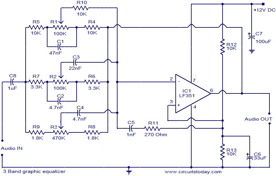
This document presents the circuit diagram of a simple three-band graphic equalizer that utilizes a single integrated circuit (IC) and a few additional components. The IC employed in this design is the LF351, which is a wide bandwidth single...
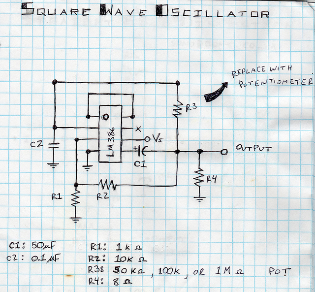
This is a square wave oscillator (digital, similar to 8-bit music). It is based on the LM386 amplifier integrated circuit, which is also the foundation for the mini guitar amplifier. The design includes a simple power switch connected to...
This circuit is designed to test the servo motor of a parabolic antenna. It functions effectively, although a system with a low-noise block feed (LNBF) is generally more suitable. Many users continue to utilize systems that employ an LNB...
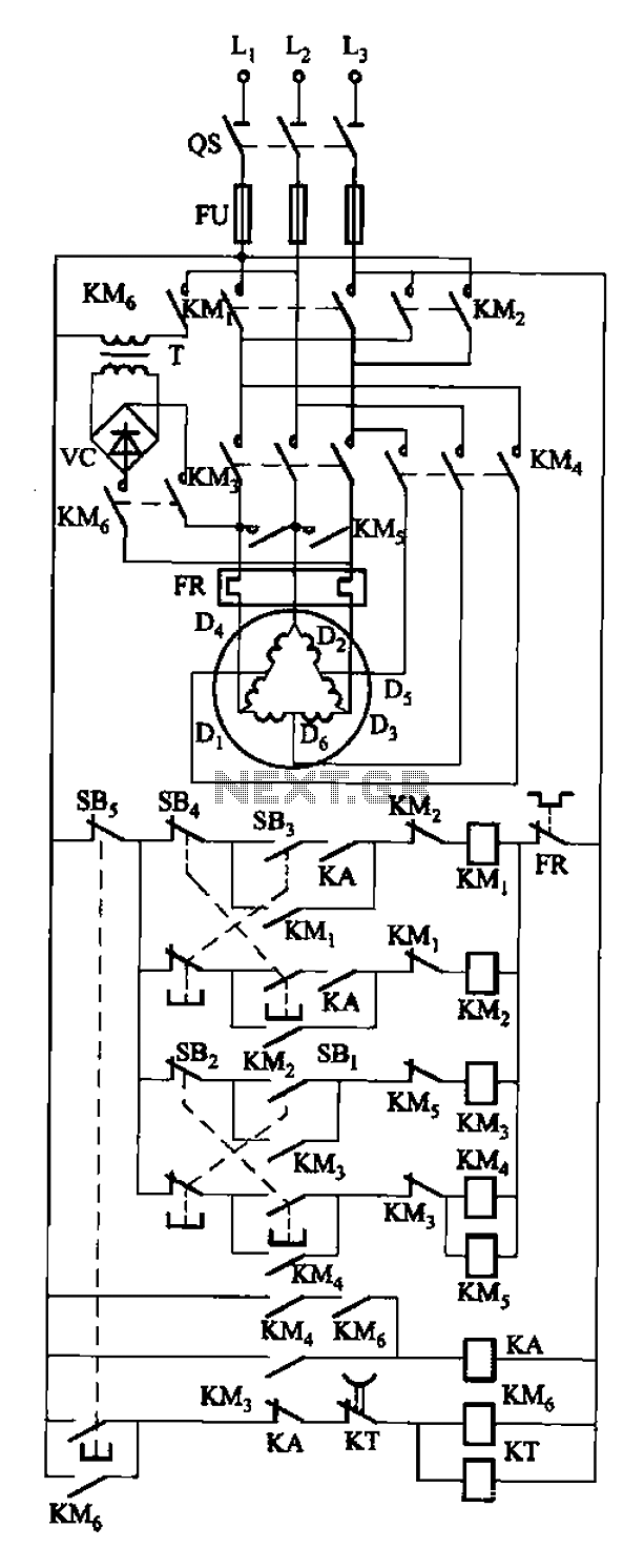
The circuit depicted in Figure 3-108 includes various control buttons: SB3 for the forward button, SI for the reverse button, SBi as the low start button, SB2 for the speed start button, and SBs for the stop button. KMs...