
40 m band direct conversion

The circuit design incorporates several key components that work together to achieve the desired functionality. The VFO (Voltage-Controlled Oscillator) generates a stable frequency signal that is essential for mixing with the RF input. The RF input bandpass filters are critical in selecting the desired frequency range, utilizing bowl resonators to ensure high selectivity and minimal loss.
The choice of the HPF505 diode mixer is significant due to its efficiency in mixing signals. The alternative mixers, IE500 and SRA1, offer flexibility in component selection, allowing for optimization based on availability and performance characteristics. The matching network, comprising R11 and the input impedance of IC1, is designed to facilitate a 50-ohm output, which is standard for RF applications, ensuring compatibility with subsequent stages and minimizing reflections.
R10 plays a pivotal role in controlling the gain of the broadband amplifier IC1. By selecting a 100-ohm resistor, a gain of 40 dB is achieved, which is substantial for amplifying weak RF signals. The careful design ensures that any unwanted RF signals are effectively shunted to ground, preventing them from interfering with the audio processing.
IC2 serves as a critical component for audio amplification, providing an additional 46 dB gain to the filtered audio signals. The passive audio filtering components at the input of IC2 are specifically chosen to allow signals around 750 Hz to pass, which is essential for audio clarity and fidelity. This selective amplification ensures that only the desired audio frequencies are enhanced, reducing noise and improving overall sound quality.
Given the high overall gain achieved by the combination of IC1 and IC2, the output level may exceed comfortable listening levels for headphones. The inclusion of the RF attenuator (P1) near the antenna input terminal is a practical solution for managing the output volume. This feature allows users to adjust the gain dynamically, ensuring a pleasant listening experience while maintaining the integrity of the received signals.
Overall, the circuit exemplifies a well-thought-out design that balances performance with usability, making it suitable for various applications in RF and audio processing.You may admit abounding of the date circuits - as they are agnate to those acclimated in some of my added projects. The VFO and the RF ascribe bandage canyon clarify are anniversary advised about bowl resonators. These are acceptable difficult to locate. [See the agenda below. ] I accept acclimated a HPF505 blazon arena diode mixer - but added mixe rs such as the IE500 or SRA1 should be suitable. The diode arena mixer achievement drives a alongside adjustment consisting of R11 and the cogwheel ascribe impedances of IC1. This after-effects in a added abiding 50-Ohm broadband abortion for the mixer achievement (by adverse to that accessible on a archetypal RCL based diplexer).
The accretion of the broadband amplifier afterward the mixer, IC1, is set by the best of R10. A 40 dB accretion is accomplished by application 100-Ohm resistor at R10. Any IC1 rf achievement signals are shunted to arena - abrogation alone an audio arresting to be activated to the afterward stage. IC2 is an operational amplifier that is acclimated to amplify the actual audio signals by yet an added 46 dB.
Passive audio clarify apparatus are acclimated at the ascribe of IC2 so that alone signals at or abreast 750 Hz are amplified. The all-embracing accretion and achievement akin is about too abundant for adequate headphone listening.
An rf attenuator (P1 amid abreast the antenna ascribe terminal) is acclimated as a agency of authoritative the receiver achievement volume 🔗 External reference
Related Circuits
This compact transmitter employs a Hartley oscillator configuration. Typically, the capacitor in the tank circuit connects to the base of the transistor; however, at VHF frequencies, the base-emitter capacitance of the transistor behaves like a short circuit, maintaining its...
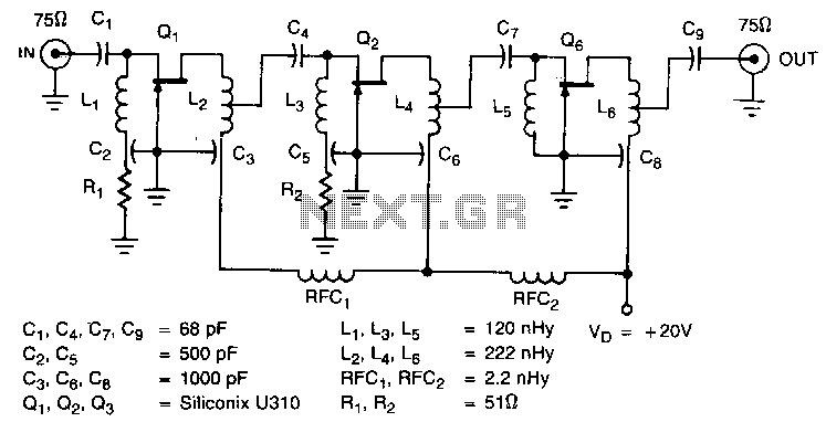
The amplifier circuit is designed for a 225 MHz center frequency, with a 1 dB bandwidth of 50 MHz, low input VSWR in a 75-ohm system, and a gain of 24 dB. Three stages of U310 FETs are utilized...
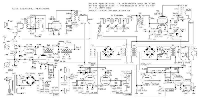
This true SSB transceiver is built around just 5 vacuum tubes, with no transistors nor ICs. Superhet receiver with AGC and S-meter drives a loudspeaker, 5W transmitter, very stable VXO uses CB crystals to cover 20m ham band. A...
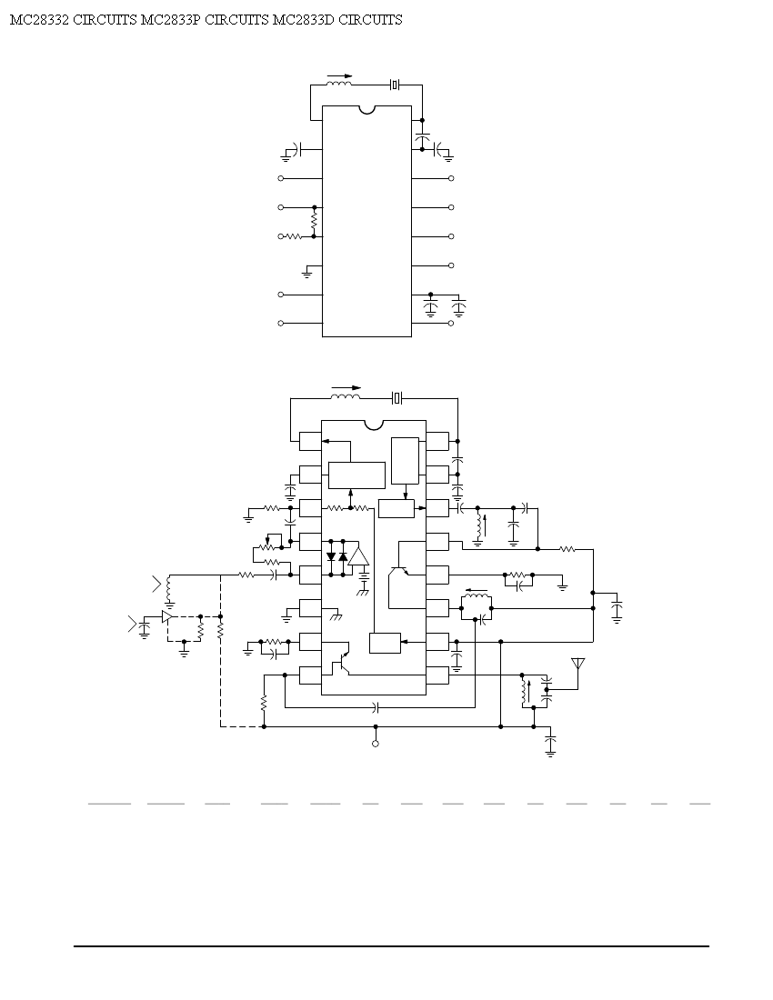
Crystal X1 operates in fundamental mode and is calibrated for parallel resonance with a load capacitance of 32 pF. The final output frequency is produced through frequency multiplication within the MC2833 integrated circuit (IC). The RF output buffer at...
A 52 MHz third overtone crystal typically has a series resonance impedance of 30 ohms as per manufacturer specifications. The crystals utilized in the prototypes exhibit nearly ten times lower series resistance but are significantly more expensive. An oscillator...
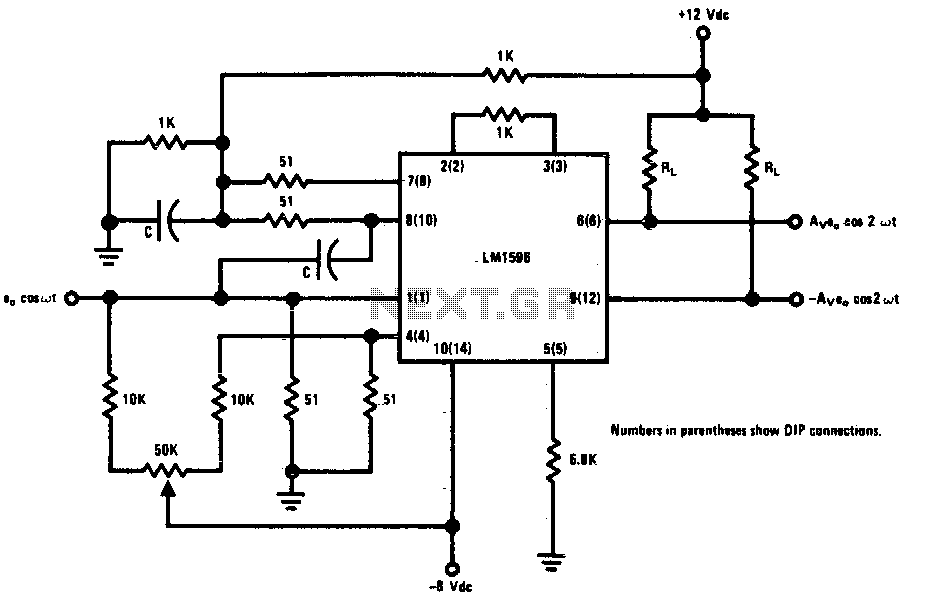
This circuit is designed to double low-level signals while maintaining low distortion. The capacitor value (C) should be selected to ensure low reactance at the operating frequency. The signal level at the carrier input should remain below 25 mV...