
Pushbutton-Controlled Power Switch

The described circuit utilizes a Silicon Controlled Rectifier (SCR) as a key component for controlling the operation of a lamp. The SCR is a semiconductor device that acts as a switch, allowing current to flow when a gate signal is applied. In this configuration, switch S1 serves as a momentary trigger that feeds a gate drive signal through resistor R1 to the SCR. This action effectively latches the SCR in the 'on' state, allowing current to flow through the connected lamp.
To ensure stability in the operation of the SCR, resistor R2 is employed to tie the gate to the cathode. This connection helps to mitigate any potential oscillations or instability issues that may arise during operation. The gate-cathode connection is crucial for maintaining a stable turn-on condition for the SCR.
Once the SCR is turned on, it remains in this state until the anode current drops below the holding current (IH) threshold. This characteristic is essential for the SCR's operation, as it requires a specific amount of current to remain conductive. To turn off the SCR, switch S2 is used to momentarily open the circuit, effectively shorting the anode and cathode terminals. This action causes the anode current to drop below the IH value, thereby turning off the SCR and extinguishing the lamp.
The design of this circuit is straightforward yet effective for applications requiring controlled lighting or power delivery. The use of resistors R1 and R2 plays a significant role in ensuring reliable performance and stability of the SCR during operation. Overall, this circuit exemplifies a practical approach to utilizing SCR technology for managing electrical loads. In both circuits, the SCR (and thereby the lamp) can be latched on by momentarily closing SI, thereby fe eding gate drive to the SC via Rl. In both circuits, the gate is tied to the cathode via R2 to improve circuit stability. Of course, after the SCR turns on, it can be turned off again only by momentarily reducing anode current below the device"s IH value. The SCR is turned off by momentarily opening S2, by using S2 to short the anode and cathode terminals of the SCR momentarily.
Related Circuits
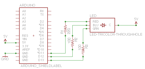
The capability to control lights and fans wirelessly has transitioned from an expensive luxury to widely accessible consumer solutions. Nevertheless, creating a custom solution remains an engaging project for hobbyists and tinkerers. RobotGrrl has developed user-friendly libraries aimed at...
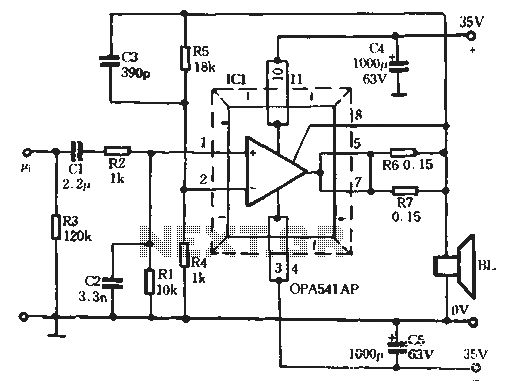
The Burr-Brown OPA541 chip is a power amplifier capable of operating with a maximum power supply voltage of 40V, delivering a continuous output current of up to 5A. The output current can be adjusted using an external resistor to...
Micropower and low-voltage operational amplifiers enable the construction of high-performance analog signal processors that do not require batteries or wall transformers. Instead, a capacitor can serve as the power source. The circuit illustrated in Figure 1 depicts an analog...
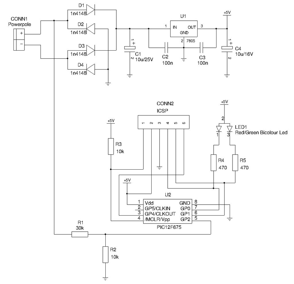
This is a compact device designed for amateur radio (HAM) enthusiasts, utilizing Powerpole connectors to interface HAM equipment with an unidentified power supply that also features Powerpole connectors. The device functions as an essential accessory for HAM radio operators,...
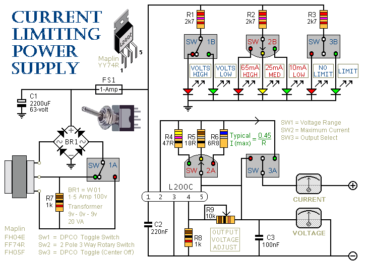
This is a 1-amp variable-voltage PSU. It adjusts from about 3v to 24v and has the added feature that you can limit the maximum output current. This is invaluable when, for example, you power-up a project for the first...

This touch switch does not rely on mains hum for switching; it can be used with battery-powered circuits. The Schmitt trigger IC1 forms a 100 kHz oscillator, and IC2a, which is biased into the linear region, amplifies the output...