
41 LED Flasher Circuit using 555 IC

The circuit employs a 555 timer in astable mode, which generates a continuous square wave output. This output can be used to drive multiple LEDs in a flashing or fading pattern, depending on the resistors and capacitors selected in the timing network. The frequency of the output can be adjusted by varying the values of the resistors (R1 and R2) and the capacitor (C1) connected to the 555 timer.
In this configuration, the output from pin 3 of the 555 timer is connected to the anodes of the LEDs, while the cathodes are connected to ground through appropriate current-limiting resistors. This ensures that each LED receives a safe amount of current, preventing damage. The timing cycle can be modified by changing the resistor and capacitor values, allowing for customization of the LED flashing rate.
Additionally, a potentiometer can be integrated into the circuit to provide a variable resistance, allowing for real-time adjustments to the flashing speed of the LEDs. This feature enhances the usability of the circuit for various applications, such as decorative lighting or visual indicators. The overall simplicity of the design makes it suitable for beginners in electronics, while still providing a platform for more experienced users to explore timing circuits and LED control.I made this as a quick project I made to use a lot of the LEDs I recently got. It basically connects via a 555 8 pin IC and allows for adjusting the t.. 🔗 External reference
Related Circuits
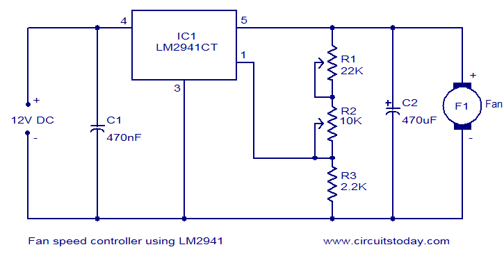
Numerous electronic circuits designed for fan speed control have been documented, and this one presents an alternative method. The circuit diagram illustrates a 12V DC fan speed controller utilizing the LM2941CT integrated circuit, which is a low dropout 1A...
Given the variety of equipment in modern home entertainment systems, the ability to adjust the gain of both audio and video signals has become essential. This particular circuit has proven to be very useful when used alongside the General...
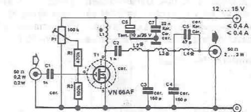
By using this RF amplifier, small power transmitters of 200 mW can be upgraded to reasonable power transmitters, ranging between 2 and 3 W. The circuit is straightforward. The output filter network suppresses noise by at least 55 dB....
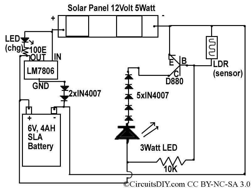
This document discusses a simple solar LED circuit. Solar panels range from 12 volts and 3 watts to larger sizes. To store energy, a 12-volt battery is required. The preferred choice is a sealed lead-acid (SLA) sealed maintenance-free (SMF)...
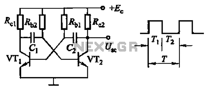
Common non-sinusoidal oscillator circuit, waveform and frequency formula - square wave oscillator - self-excited multivibrator The common non-sinusoidal oscillator circuit, specifically the square wave oscillator, is a fundamental electronic circuit utilized to generate square wave signals. It operates based on...
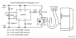
This is a simple freeze protector circuit diagram, also known as a timing circuit. It serves as a hobby project for beginners. This circuit can automatically operate any device after a fixed time once AC power supply is restored....