
4040B LED Counter

In this circuit, a counter is utilized to count the number of input pulses. The output of the counter is connected to a light-emitting diode (LED), which serves as a visual indicator of the pulse count. When pulses are received at the input, the counter increments its count, and each increment can be represented by the LED's illumination.
To design this circuit, the following components are typically used:
1. **Counter IC**: A digital counter IC, such as the 4017 decade counter or a binary counter like the 74HC393, is employed to count the incoming pulses. The counter IC will be powered by a suitable voltage supply, typically between 3V to 15V, depending on the specific IC used.
2. **Input Signal**: The input signal can be generated from various sources, such as a switch, a sensor, or a waveform generator. The input pulses should be within the operational frequency range of the counter IC.
3. **LED**: The LED is connected to one of the output pins of the counter. A current-limiting resistor is also required in series with the LED to prevent excessive current from flowing through it, which could damage the LED. The resistor value can be calculated based on the supply voltage and the forward voltage drop of the LED.
4. **Power Supply**: A stable power supply is essential for the reliable operation of the circuit. The voltage should match the requirements of both the counter IC and the LED.
In operation, as the input pulses are received, the counter increments its output. The LED will light up each time the counter reaches a specific output state, providing a clear visual indication of the pulse count. This setup is particularly useful in applications where monitoring pulse counts visually is necessary, such as in educational demonstrations or simple counting applications.
Overall, this circuit effectively combines digital counting with a visual output, facilitating easy monitoring of pulse activity.The number of the pulses of the input can be confirmed by seeing it with the eyes by putting the light-emitting diode to the output of the counter .. 🔗 External reference
Related Circuits
These small electronic lamps are quite practical and have a long lifespan. Approximately 40 years after Nick Holonyak invented the first LED, they have become nearly essential. Any dedicated electronics enthusiast typically keeps a few in their collection. Prior...
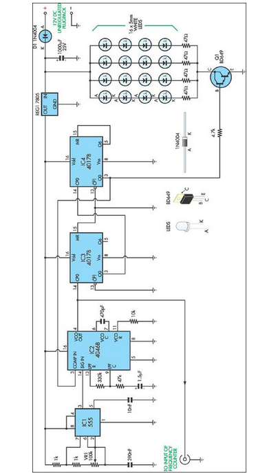
This stroboscope circuit utilizes 16 high-brightness white LEDs housed within a torch structure. It also offers a signal output to a frequency counter to indicate revolutions per minute (RPM). The stroboscope circuit is designed to provide visual indication of rotating...

More: The input data contains a brief description with no additional context or information provided. In the realm of electronics, a circuit schematic typically serves as a visual representation of an electrical circuit. It illustrates the various components such...
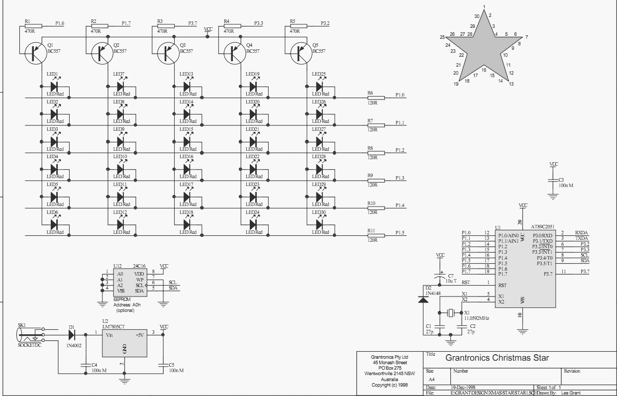
Using a PC parallel port to control external devices is a popular approach these days but I certainly couldn’t afford to tie up a PC for the few weeks leading up to Christmas just to flash a few LEDs!...

An electret microphone feeds a bandpass filter circuit (IC1A), which subsequently drives a comparator. This comparator activates Q1, a switch that conducts when audio signals from IC1B cause D1, C4, R6, and R7 to bias it ON. The circuit begins...
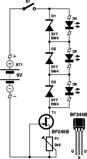
The circuit was designed to work with an audio power amplifier which operated off +18v-0v-18v power rails. The actual voltage used is not too critical except that the feedback is referred to the LED chain which itself is anchored...