
Audio 10 LED VU meter

Clearly the calibration is going to be affected by the LED operating voltages: green LEDs are higher voltage than reds and high brightness LEDs drop more voltage than low. However my experience is that any particular make/type of LED are very consistent in voltage.
This circuit was evolved quite some while ago for an audio mixing desk and it was put into production. We were at that time trying to find an IC which would do the job. Once again the circuit using mostly discrete transistors worked out easier. This was however about 15 years ago and there are newer ICs which will do the job. However when I designed this circuit these were new and quite expensive.
This is a circuit which 4QD could manufacture and sell if there were sufficient demand so if you do have a quantity application please contact us. Let me know if you have any queries or how you get on with it!
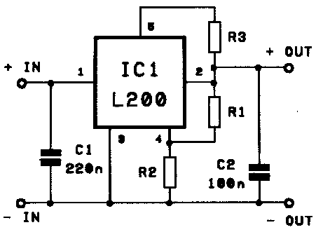
The circuit is constructed to operate with an audio power amplifier, utilizing dual power rails of +18V and -18V, with a ground reference. The design incorporates a feedback mechanism that references the LED chain to a +12V rail, necessitating a dedicated voltage stabilizer for optimal operation. A notable feature of this circuit is its series configuration of LEDs, allowing for a constant current draw of 20mA, regardless of the number of illuminated LEDs. This configuration enhances efficiency and simplifies the design compared to parallel LED arrangements.
The circuit includes two operational amplifiers (op-amps) configured as a rectifier to process the audio input signal. This rectification enables the circuit to accurately measure the audio level, which is crucial for applications like audio mixing where signal levels must be monitored. A changeover switch is integrated to toggle between average and peak reading modes, providing flexibility in signal monitoring.
The third op-amp stage implements a logarithmic scale through a five-stage feedback circuit. This stage is particularly important for visual representation of audio levels, as it allows for a more intuitive understanding of varying signal amplitudes. The feedback is dynamically adjusted based on the operating voltages of the LEDs, with diodes and resistors managing the feedback loop to the positive input of the op-amp.
Calibration of the circuit is influenced by the forward voltage drop of the LEDs used, which varies by color and brightness. Green LEDs typically exhibit a higher forward voltage than red LEDs, while high-brightness LEDs may have a greater voltage drop compared to their low-brightness counterparts. However, consistency in voltage drop is generally observed within specific LED types, allowing for reliable calibration.
Originally developed for an audio mixing desk, this circuit has proven effective and has been produced for commercial use. While there are now more modern integrated circuits available that could potentially simplify the design, the discrete transistor approach employed in this circuit was practical and cost-effective at the time of its creation. The design remains viable for production if there is sufficient demand, indicating potential for further applications in audio engineering.The circuit was designed to work with an audio power amplifier which operated off +18v-0v-18v power rails. The actual voltage used is not too critical except that the feedback is referred to the LED chain which itself is anchored to a +12v rail, hence the separate stabilizer for this.
It has one large advantage over most of the LED chips available - all the LEDs are in series so it only draws 20mA irrespective of the number of LEDs illuminated. The two input op-amps form a rectifier circuit to rectify the audio input level. The changeover switch converts the circuit from average reading to peak reading. The third opamp stage gives a logarithmic scale: it does this by means of a 5 stage feedback circuit. The various stages of feedback are switched in by the LED operating voltages and the diodes and resistors feeding back to the +ve input os the op-amp.
Clearly the calibration is going to be affected by the LED operating voltages: green LEDs are higher voltage than reds and high brightness LEDs drop more voltage than low. However my experience is that any particular make/type of LED are very consistent in voltage. This circuit was evolved quite some while ago for an audio mixing desk and it was put into production.
We were at that time trying to find an IC which would do the job. Once again the circuit using mostly discrete transistors worked out easier. This was however about 15 years ago and there are newer ICs which will do the job. However when I designed this circuit these were new and quite expensive. This is a circuit which 4QD could manufacture and sell if here were sufficient demand so if you do have a quantity application please contact us. Let me know if you have any queries or how you get on with it! 🔗 External reference
Related Circuits
Here's how to make a good charger for a sealed lead-acid battery (this will NOT work with NiCad batteries) that’s faster (because it allows more current into the battery initially) and safer (because it uses lower voltage when the...
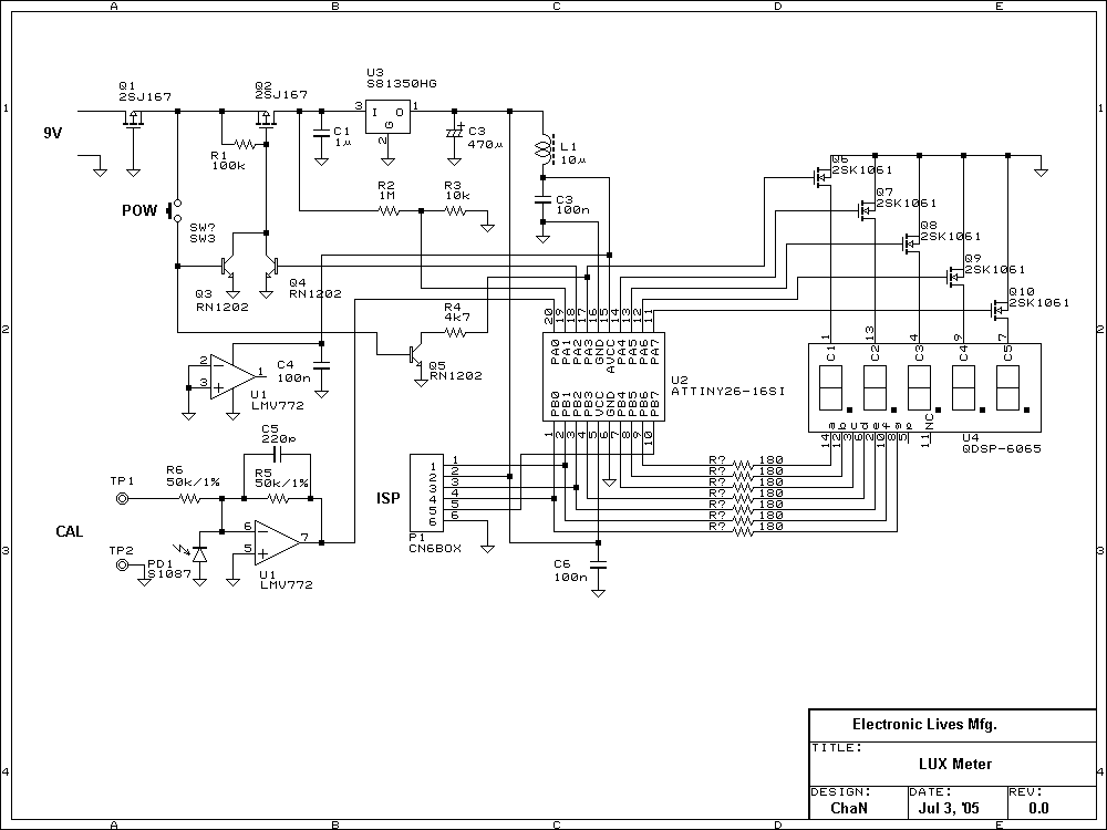
Photo diode outputs light current that is well proportional to input light power when it is used in short mode. In this lux meter, the output current is converted to voltage with an I-V converter, it is captured by...

This circuit is simple and inexpensive, which is its primary advantage. Although the output power is not high, the audio quality is good due to the TDA1910's low noise characteristics. This circuit is suitable for use as a student...
The RF engineer often needs an instrument that can reliably and quickly check a low-frequency quartz crystal unit. However, such equipment is challenging to find, and engineers frequently refer to electronic circuit handbooks for schematics that can perform this...
The BQ2000 is a programmable, monolithic integrated circuit designed for fast-charge management of nickel cadmium (NiCd), nickel metal-hydride (NiMH), or lithium-ion (Li-Ion) batteries in single or multi-chemistry applications. The BQ2000 detects the battery chemistry and employs optimal charging and...
A simple count-down LED timer that counts in minutes and seconds. Three buttons below the LED provide control of the unit, allowing you set the desired countdown time in minutes and seconds and a start/stop button. Completion of the...