
40m TRANSMITTER
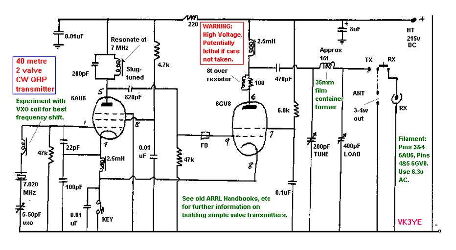
The 40-meter transmitter described utilizes two vacuum tubes, specifically the 6AU6 and 6GV8, to generate radio frequency signals for amateur radio communication. The 6AU6 is a pentode tube often used in RF amplification, while the 6GV8 is a dual triode that can be employed for oscillator and amplifier functions within the circuit.
The design of this transmitter is relatively straightforward, making it accessible for hobbyists and engineers with basic knowledge of electronics. However, caution is advised due to the presence of high voltages, which are typical in tube-based circuits. Proper insulation, safety equipment, and adherence to standard electrical safety practices are essential during construction and operation.
The transmitter's performance can be optimized by experimenting with a Variable Crystal Oscillator (VXO) coil, which allows for fine-tuning of the operating frequency. This adjustment is crucial for achieving the desired frequency shift and maintaining stability in transmission. For those seeking additional insights and guidance, consulting older editions of the ARRL Handbooks is recommended, as they provide valuable information on the principles of valve transmitters and practical construction techniques.
In terms of circuit design, the transmitter will typically include a power supply section to provide the necessary high voltage for the tubes, along with signal coupling components, such as capacitors and resistors, to ensure proper operation. An output stage will be necessary to match the transmitter to an antenna, facilitating effective transmission of the radio signals generated by the tube oscillators.This is a 40 meter transmitter which uses two valves, the 6AU6 and 6GV8. The construction is easy. Just be carefull due to high voltage present. Experiment with VXO coil for best frequency shift. See old ARRL Handbooks for further information on building simple Valve transmitters. 🔗 External reference
Related Circuits
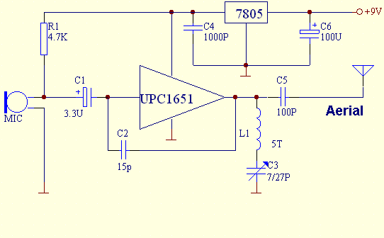
This FM transmitter is built with UPC1651, which is a silicon monolithic integrated circuit specifically designed as a wideband amplifier covering the HF band. The UPC1651 is a versatile integrated circuit that serves as a key component in FM transmitter...
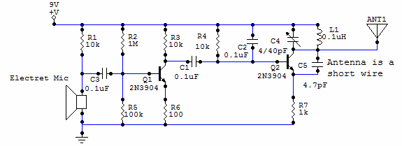
This circuit uses a small microphone to capture the sound and some transistors to generate radio waves that can be picked up by a FM receiver like a car stereo. The first part is the microphone and some resistors...
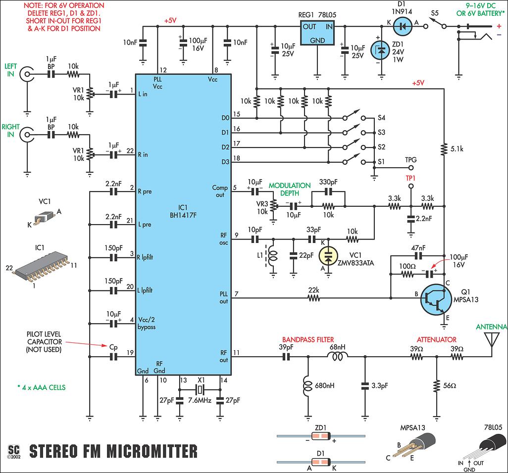
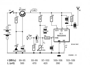
This new stereo FM Micromitter is capable of broadcasting good quality signals over a range of about 20 meters. It is ideal for broadcasting music from a CD player or from any other source so that it can be...
FM transmitter IC manufacturers and suppliers include FM transmitter IC manufacturers with Bluetooth capabilities. The FM transmitter features an integrated circuit with four channels. The TNA029 IR audio transmitter IC is a low-cost solution with high performance. The FM transmitter...
These do-it-yourself FM transmitters are relatively simple to construct and provide a satisfying experience when music is played through the radio receiver. Comments and links to additional designs that are not included in the best list are welcome. FM transmitters...
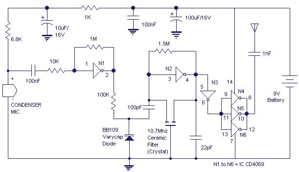
The gate N1 serves as a buffer to amplify the signals from the condenser microphone. The inverter N2, along with its associated components, creates a radio frequency oscillator operating in the FM range. The varicap diode BB109 is utilized...