
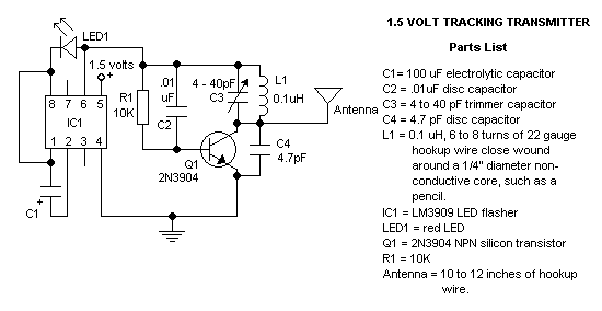
Versatile FM Transmitter

The circuit begins with the condenser microphone, which captures sound waves and converts them into electrical signals. The output from the microphone is typically weak, necessitating amplification. This is where gate N1 functions as a buffer amplifier, providing the necessary gain to strengthen the microphone's output signal for further processing.
Following the buffer stage, inverter N2 is configured to form a radio frequency oscillator. This oscillator is critical as it generates the carrier wave needed for frequency modulation. The design of this oscillator includes passive components that determine its frequency of operation within the FM band. The stability and frequency accuracy of this oscillator are essential for effective modulation and signal transmission.
The varicap diode BB109 is a key component in the modulation process. It is a variable capacitance diode whose capacitance changes with the applied reverse voltage. By integrating this diode into the circuit, the audio signal from the microphone can modulate the frequency of the carrier wave generated by inverter N2. This modulation process is fundamental in transmitting the audio signal over radio frequencies, allowing it to be received by compatible FM receivers.
Inverters N4, N5, and N6 are employed to drive the antenna, which is responsible for radiating the modulated signal into the air. These inverters are connected in parallel, which significantly reduces the overall output impedance of the stage. This low impedance is advantageous as it allows for efficient power transfer to the antenna, enhancing the transmission range and effectiveness of the circuit. The arrangement ensures that the combined output can effectively drive the antenna without significant signal loss, resulting in a robust and reliable FM transmission system.The gate N1 acts as a buffer for strengthening the signals from the condenser microphone. The inverter N2 with its associated components forms a radio frequency oscillator in the FM region. The varicap diode BB109 is used for frequency modulating the audio signal to the carrier wave generated by the oscillator. Inverters N4 t0 N6 are used to drive t he antenna. As the N4, N5, N6 are connected in parallel their effective output impedance is very less and can easily drive the antenna. 🔗 External reference
Related Circuits

In May 2002, Silicon Chip introduced the "Battery Guardian," a project aimed at safeguarding 12V car batteries from over-discharge. This unit has gained significant popularity and remains available from kit suppliers. The new design does not replace the Battery...
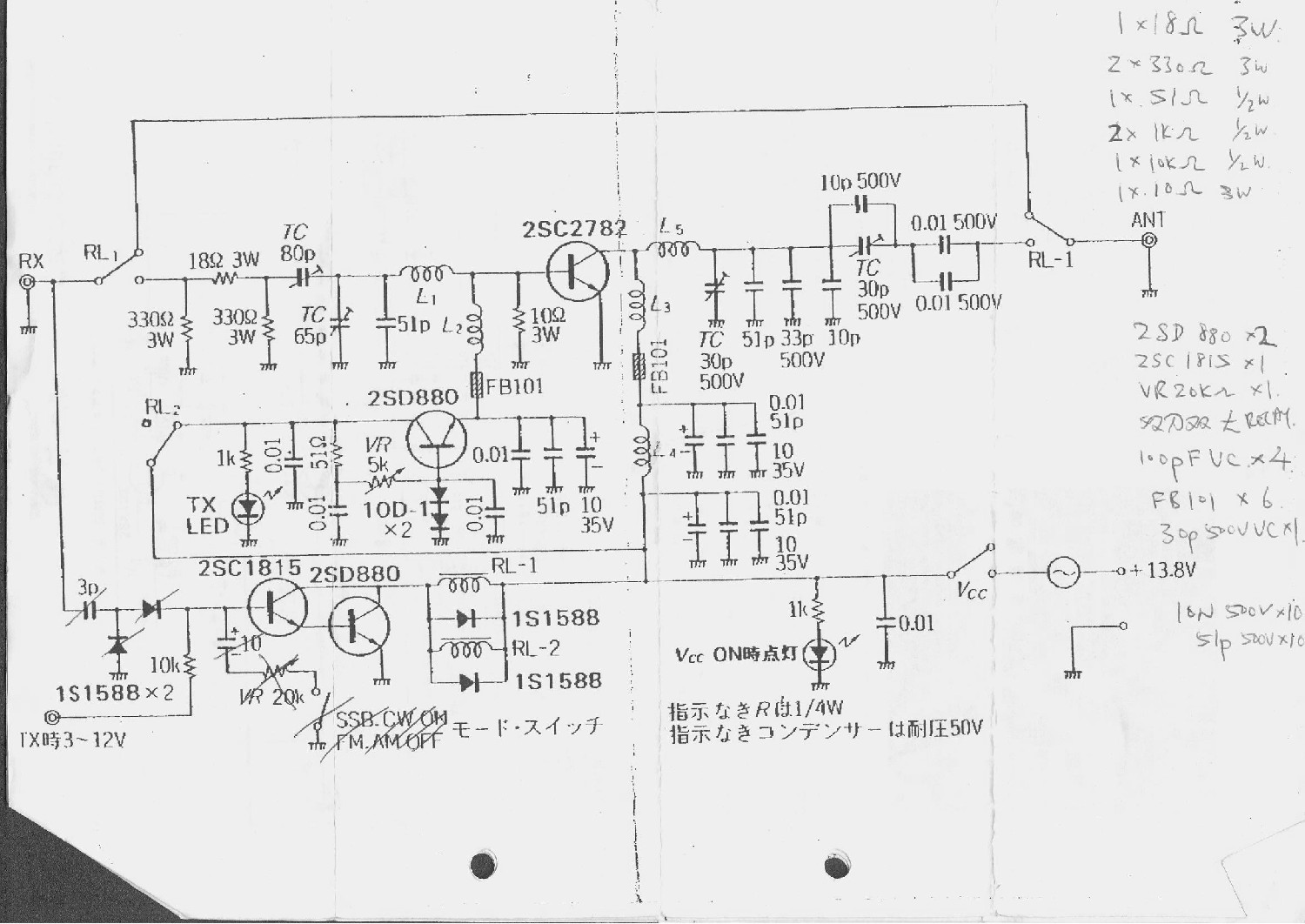
This is a 6-meter band transmitter RF power amplifier (50 MHz) with a 100W output. It is compatible with the FT-736R and is driven by a 10W signal for 6m SSB DX. The construction information is sourced from Japan...
The circuit is a common form used in FM transmitters. The transistor conducts for 60-90 electrical degrees. When it turns off the LC tank rings, completing the sinusoidal waveform coupled to the antenna. The circuit is 77-85% efficient, compared...
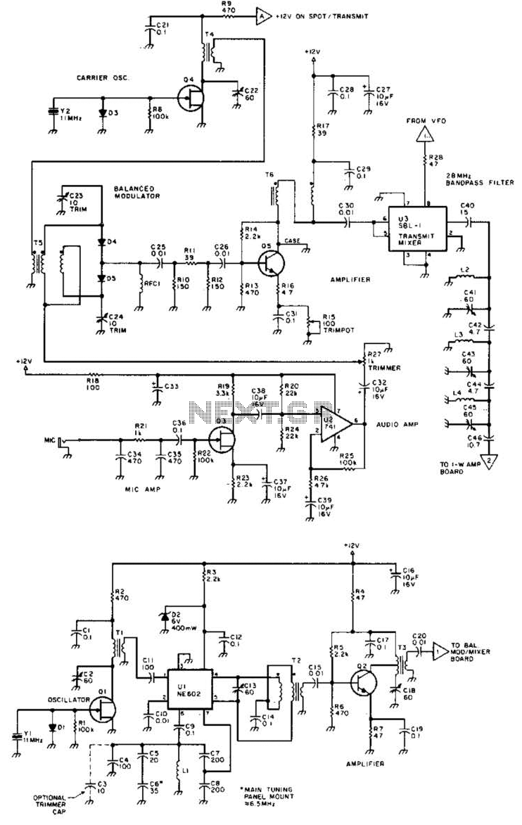
Using a Motorola MC2833 one-chip FM transmitter, a few support components, and an MPF6660 FET RF amplifier, this transmitter delivers approximately 3 W into a 50-ohm load. It is capable of operation over a frequency range of about 29...
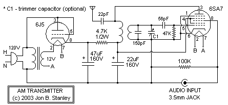
A functional AM transmitter has been completed, primarily based on Phil's Li'l 7 Transmitter design. Achieving oscillation in LC-based transmitters can be challenging without the correct combination of tubes and coils. This transmitter utilizes a 6J5 and a 6SA7...
A simple USB FM transmitter that can be used to play audio files from an MP3 player or computer on a standard VHF FM radio by connecting it to a USB port. The circuit does not require any coils...