
UPC1651 FM Transmitter

The UPC1651 is a versatile integrated circuit that serves as a key component in FM transmitter designs, particularly in the high-frequency (HF) range. This IC is engineered to provide excellent amplification characteristics, making it suitable for applications requiring wide bandwidth and high linearity.
In a typical FM transmitter circuit utilizing the UPC1651, the configuration may include an input stage for modulating audio signals onto a carrier frequency. The circuit often comprises additional components such as resistors, capacitors, and inductors, which are used to set the operating frequency and to filter unwanted harmonics.
The UPC1651 operates efficiently within the HF band, typically from 3 MHz to 30 MHz, allowing it to accommodate various broadcasting needs. The design may include a feedback mechanism to stabilize the gain and improve linearity, ensuring that the transmitted signal maintains fidelity and clarity.
Power supply considerations are crucial in the design, as the UPC1651 requires a stable voltage source to function optimally. Bypass capacitors are commonly employed to filter out noise from the power supply, enhancing the overall performance of the transmitter.
In summary, the UPC1651 FM transmitter circuit is an effective solution for high-quality audio broadcasting within the HF band, leveraging the capabilities of a specialized silicon monolithic integrated circuit for enhanced performance.This fm transmitter is build with UPC1651 which is a silicon monolithic integrated circuit especially designed as a wide band amplifier covering the HF ban.. 🔗 External reference
Related Circuits
This circuit is a simple two transistor (2N2222) FM transmitter. No license is required for this transmitter according to FCC regulations regarding wireless microphones. If powered by a 9 volt battery and used with an antenna no longer than...
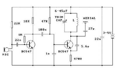
Place the transmitter approximately 10 feet away from an FM radio. Set the radio to a frequency between 89 and 90 MHz. Walk back to the FM transmitter and turn it on. Separate the windings of the coil by...
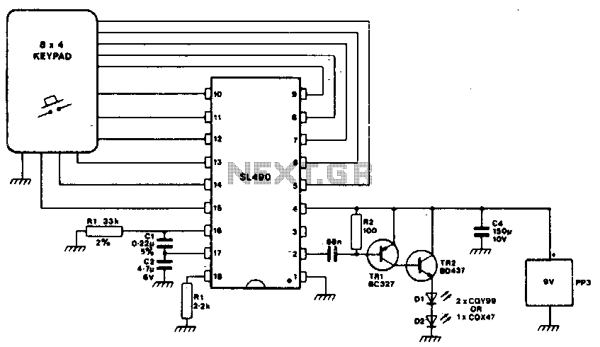
This simple infrared transmitter uses the PPM output from pin 2 of the SL490, which is connected to the base of the PNP transmitter TR1. It generates an amplified current pulse approximately 15 microseconds wide. This pulse is further...
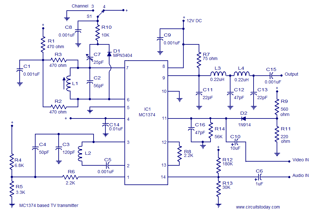
A simple TV transmitter circuit utilizing the TV modulator circuit IC MC1374. It operates with a 12V supply and is capable of broadcasting on channel 3 or 4, employing FM modulation for sound transmission. The TV transmitter circuit based on...
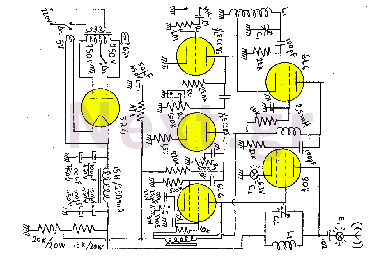
This transmitter consists of a total of five bulbs. The 6L6 tube functions as an oscillator, directing oscillations to the grid of the 807 tube, which serves as the final amplifier and the transmitter output lamp. The amplifier includes...

3V FM Transmitter Circuit. This project provides the schematic and the parts list needed to construct a 3V FM transmitter. This FM transmitter is... The 3V FM transmitter circuit is designed to operate at a low voltage, making it suitable...