
freeze protector circuit

The freeze protector circuit is designed to activate a connected device after a predetermined delay when AC power is restored. This functionality is particularly useful in applications such as preventing pipes from freezing in cold weather by activating heaters or other protective devices.
The circuit typically consists of the following components: a timer IC (such as the NE555), a relay, resistors, capacitors, and a diode for flyback protection. The timer IC is configured in a monostable mode, where it generates a single output pulse when triggered. The duration of this pulse is determined by the resistor and capacitor values connected to the timer.
Upon restoration of AC power, the timer IC is triggered, initiating a countdown based on the RC time constant. After the specified time elapses, the output pin (pin 3 of the IC) goes high, energizing the relay. The relay acts as a switch, allowing current to flow to the connected device, thus activating it.
The 10k ohm resistor connected to the output pin serves to limit the current flowing into the relay coil, ensuring that the relay operates safely within its specifications. The 12-volt relay allows for control of higher voltage devices while being driven by the low voltage output from the timer.
To protect the circuit from voltage spikes generated when the relay coil is de-energized, a flyback diode is placed in parallel with the relay coil. This diode allows the back EMF generated by the collapsing magnetic field of the relay coil to safely dissipate, preventing damage to the timer IC.
Overall, this simple freeze protector circuit is an effective and low-cost solution for automating device operation based on the presence of AC power, making it an excellent project for electronics enthusiasts and beginners.This is the simple freeze protector circuit diagram. It is also called timing circuit. It is just hobby project for beginners. When you need to operate automatically any device in the fixed time later after coming AC power supply, you can use this circuit. The circuit output pin 3 is connected with resistor (10k) and output 12 volt relay. Relay is connected as figured with the device. Making cost is too low. Anyone can make this circuit easily. 🔗 External reference
Related Circuits
This circuit is a compact +5V power supply that is beneficial for digital electronics experimentation. Inexpensive wall transformers with variable output voltage can be found at electronics shops and supermarkets. While these transformers are readily available, their voltage regulation...
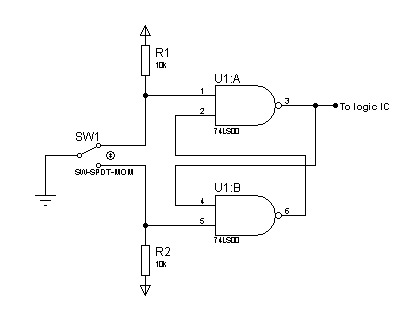
In most digital electronics projects that utilize various types of switches, switch bounces are frequently encountered. These are additional glitches that occur following the actual operation of the switch. These small pulses can disrupt the proper functioning of the...
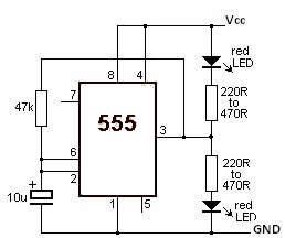
This LED flasher circuit utilizes a 555 timer integrated circuit (IC). The circuit diagram is straightforward and requires only a few external components. When operational, the red LEDs will flash sequentially at a predetermined frequency, similar to the indicators...
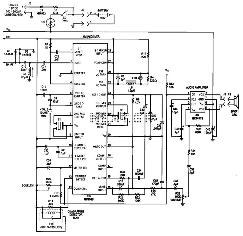
Using a Motorola MC3363 LSI one-chip FM receiver, the circuit is a dual-conversion FM receiver with a 10.7-MHz IF chain. IC4 provides power to drive a small speaker. The described circuit employs the Motorola MC3363 integrated circuit, which is designed...

The ordinary triode 3DA87C is utilized to create a long-range FM transmitter circuit, which functions as a standard three-point oscillator circuit. This remote transmitter circuit is capable of large current emissions, achieving a range of up to 1 kilometer...
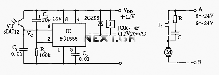
The control circuit consists of an NE555 timer and a phototransistor, along with resistors R1, capacitors C1 and C2, among other components. The photodiodes 3DU12 respond to sunlight by decreasing their resistance, which causes the voltage at the 555...