
3 band equalizer

This three-way tone control circuit is designed to enhance or attenuate specific frequency bands in an audio signal, providing flexibility for sound shaping in various audio applications. The circuit typically consists of three separate filters: a low-pass filter for low frequencies, a band-pass filter for mid frequencies, and a high-pass filter for high frequencies. Each filter can be independently adjusted to either boost or cut the respective frequency range.
The operational amplifiers (op-amps) serve as the main active components in the circuit, allowing for precise control over the gain of each frequency band. The use of feedback resistors and capacitors in conjunction with the op-amps enables the user to achieve the desired frequency response. The ± 18 dB/octave specification indicates that the gain can be increased or decreased by 18 decibels per octave, providing a steep slope for frequency adjustments.
Power supply considerations are crucial for the operation of the circuit. While it is designed to work with a dual power supply of ± 15V, the option to use a single supply voltage of +9V to +30V expands its versatility. In single-supply configurations, additional coupling and biasing components may be required to ensure that the op-amps operate within their linear range without distortion.
This tone control circuit can be implemented in various audio devices, such as mixing consoles, amplifiers, and equalizers, where precise frequency management is essential for achieving optimal sound quality. Proper layout and component selection are important to minimize noise and distortion, ensuring that the integrity of the audio signal is maintained throughout the processing stages.A classic circuit of regulation of tone of three way, with which we can regulate low, mid and high frequencies, of acoustic signal. The boost/cut can be regulated in the range of ± 18 dB/oct. In the circuit the supply is ± 15V, but can be also supplied with alone supply + 9 until + 30.. 🔗 External reference
Related Circuits
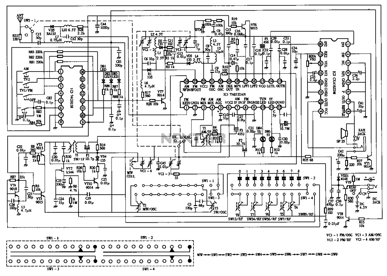
The circuit diagram for the Desheng 119 700 type FM, TV sound, medium wave, and short wave high sensitivity L2-band stereo radio is presented below. The Desheng 119 700 type radio circuit is designed to receive various frequency bands including...
This section discusses a series of 5-band equalizer circuits utilizing a single integrated circuit (IC) BA3812L, which is designed for high-fidelity (hi-fi) audio applications. The BA3812 IC features a 5-point equalizer with all functions integrated within the chip. The...
The described circuit is a graphic equalizer, characterized by ten adjusting potentiometers. Each of these potentiometers influences a specific frequency range, with the central frequency of each range being an octave (double) away from the central frequencies of adjacent ranges....
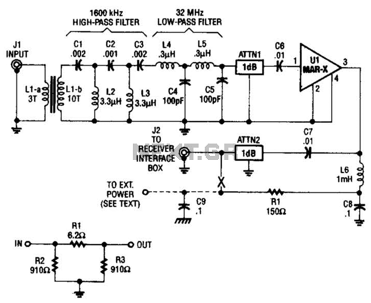
The HF/SW receiver preamplifier consists of a broadband toroidal transformer (LI-a and Ll-b), an LC network featuring a 1600-kHz high-pass filter and a 32-MHz low-pass filter, inductors L2 and L3 (26 turns of #26 enameled wire wound on an...
The lower FET operates in common source mode, while the upper FET operates in common gate mode, achieving full high-frequency gain. The bottom FET is tunable, allowing for peak adjustment for a particular station. Coil details follow: The described circuit...
This wideband jammer simultaneously blocks all transmissions within a desired band by sweeping across the specified frequency range, starting from the lowest frequency to the highest. A linear sawtooth signal is applied to the modulator in the FM transmitter....