
43925 MHz ATV DOWNCONVERTER

The described converter is designed to facilitate the transmission of amateur television signals by leveraging the characteristics of double sideband modulation. By focusing on the lower sideband, the converter minimizes interference, particularly in environments where multiple repeaters are present within the specified frequency range. This is particularly advantageous in crowded RF environments, where the potential for signal overlap and interference is high.
The circuit typically includes a mixer stage that combines the input DSB signal with a local oscillator signal, effectively shifting the frequency to the desired output band. Filters are employed to isolate the lower sideband while attenuating unwanted frequencies, including the upper sideband and any spurious signals that may arise from the mixing process.
The choice of components, such as low-noise amplifiers and high-quality filters, is critical to maintaining signal integrity and minimizing distortion. The design must also account for the potential for VHF image responses, particularly from adjacent channels like channel 29. This necessitates careful frequency planning and possibly the inclusion of additional filtering stages to mitigate such interference.
Overall, the implementation of this converter is essential for amateur television operators seeking to optimize their transmission capabilities while navigating the challenges posed by existing commercial broadcast signals and other RF interferences.Most ATV (Amateur Television] transmitters transmit a DSB signal and commercial television stations use a VSB (Vestigial Sideband) signal. This fact is made use of in this converter to use the lower sideband. This results in less interference from repeaters that occupy the 440- to 445-MHz por-tion of the band.
However, this approach might suffer f rom VHF image responses from channel 29, if that channel is active in your area. 🔗 External reference
Related Circuits
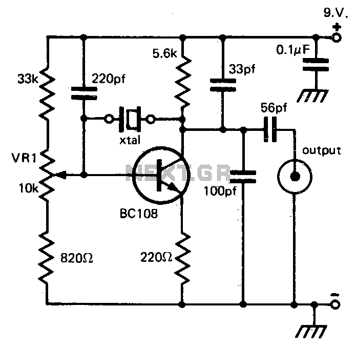
This circuit provides reliable oscillation and an output close to one volt peak-to-peak. Power consumption is around 1 mA from a nine-volt supply. The described circuit is likely a simple oscillator designed to generate a periodic waveform with a peak-to-peak...
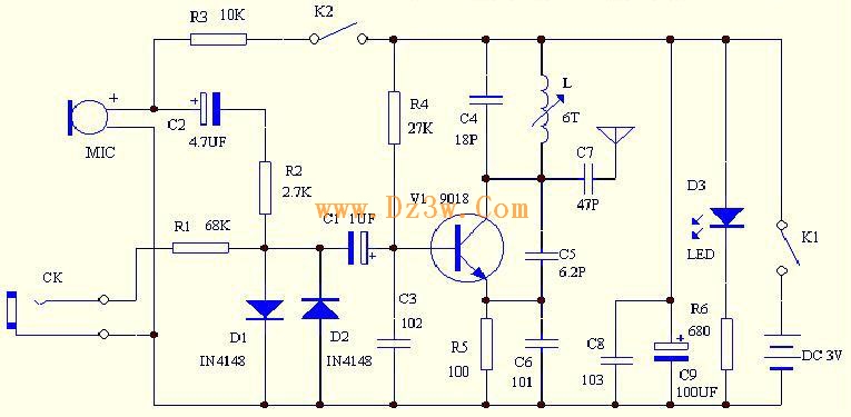
C4 and L form a resonator, where the resonant frequency corresponds to the FM transmitting power of the microphone. According to the component parameters in the diagram, the transmission frequency can range from 88 to 108 MHz. The frequency...
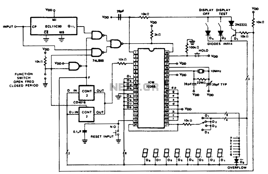
The figure illustrates the application of a CD4016 analog multiplexer to route digital outputs back to the FUNCTION input. The CD4016 functions as a digitally controlled analog transmission gate, eliminating the need for level shifting of the digital output....
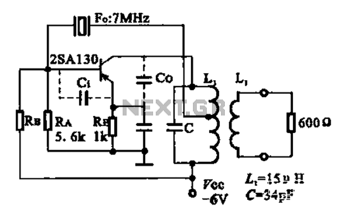
The 2SA130 transistor is used in an oscillator circuit with an oscillation frequency of 7 MHz. The power supply voltage is 6V, and the load is a frequency-selective resonant circuit with a quality factor of 600. The circuit utilizes the...

The multifunction frequency meter is an instrument that can measure various parameters on a single display using an 8-digit 7-segment LED. The controls measure... The multifunction frequency meter is designed to provide accurate measurements of frequency, voltage, current, and other...
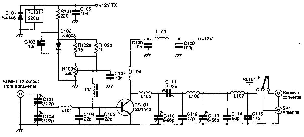
This 70 MHz RF power amplifier circuit utilizes the SD1143 transistor, which offers a gain of approximately 14 dB in this configuration. The design leverages the characteristics of a 175 MHz device. The RF power amplifier circuit designed around the...