
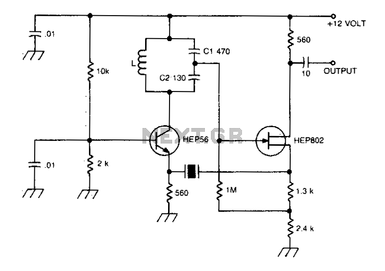
96Mhz crystal oscillator

The described circuit is likely a simple oscillator designed to generate a periodic waveform with a peak-to-peak voltage of approximately one volt. The oscillation can be achieved through various methods such as using a relaxation oscillator, a Colpitts oscillator, or a simple RC oscillator configuration.
The power supply requirement is specified as nine volts, which suggests that the circuit may be powered by a standard battery or a regulated power supply. The low power consumption of around 1 mA indicates that the circuit is efficient, making it suitable for battery-operated devices or applications where power conservation is critical.
The output waveform can be utilized in various applications, including signal generation for testing purposes, clock signals for digital circuits, or as a modulation source in communication systems. The circuit's design should ensure stability and reliability in its oscillation performance, possibly incorporating feedback mechanisms to maintain consistent output characteristics.
In practical implementations, components such as resistors, capacitors, and transistors (or operational amplifiers) are typically used to define the oscillation frequency and shape of the output waveform. The choice of components and their values will significantly influence the performance of the circuit, including factors like frequency stability, output amplitude, and waveform distortion.
Overall, this circuit represents a fundamental building block in electronics, demonstrating the principles of oscillation and signal generation with a focus on low power consumption and manageable output levels.This circuit provides reliable oscillation and an output dose to one volt peak-to-peak Power consumption is around 1 mA from a nine volt supply.
Related Circuits
Achieving the appropriate amplifier loop gain is a significant challenge in generating a low distortion, constant amplitude sine wave. Nevertheless, this issue can be addressed with... Amplifier loop gain is a critical parameter in the design of audio and signal...
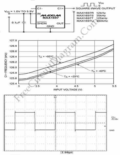
This circuit generates a square wave, which is useful as a clock signal or AC drive for the excitation of sensors. This article presents a square wave. The square wave generator circuit is designed to produce a periodic waveform that...
A typical Butler oscillator operating within the frequency range of 20 to 100 MHz incorporates a Field Effect Transistor (FET) in the second stage of its configuration. The circuit exhibits reliability issues when utilizing two bipolar transistors. In some...
The output frequency can be altered based on the division ratio of the comparison frequency in the 10 kHz unit, with the division ratio set to 1024 in this circuit. Given that the amateur radio bandwidth in Japan is...
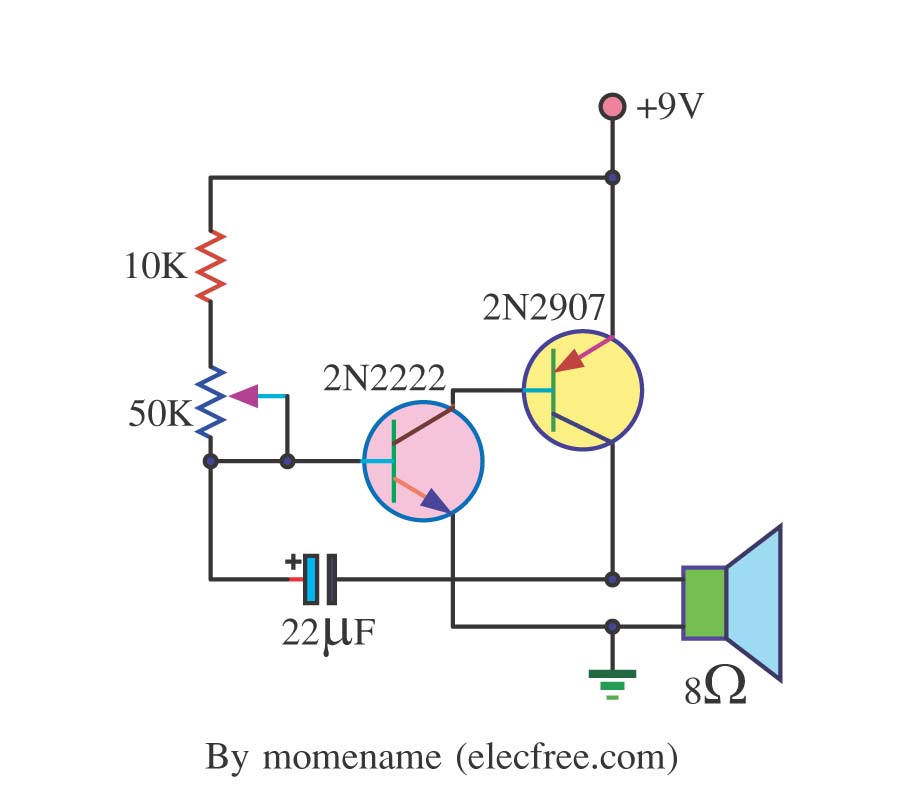
This is a simple tone oscillator generator. It uses the transistors 2N2222 and 2N2907 as the main components. The tone sound is controlled with a 50K ohm resistor (R2) and an 8-ohm speaker is utilized. The tone oscillator generator circuit...
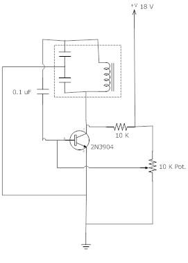
The frequency remains stable as the voltage decreases. It is referred to as the "backwards JT" because it operates optimally with a bifilar coil and a single transistor. With a modification to the circuit, it is possible to deplete...