
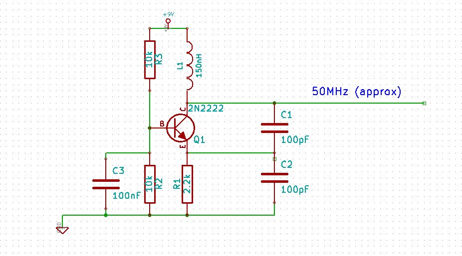
49MHz Toy RF Transmitter

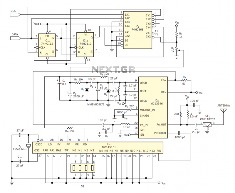
The remote control tarantula transmitter circuit is designed to operate in the 49.86 MHz frequency band, which is commonly used for low-power, short-range communication devices. The circuit typically includes key components such as a transmitter module, an oscillator, and various passive components that assist in signal modulation and transmission.
The transmitter module is responsible for generating the RF signal at the specified frequency, while the oscillator ensures that the signal remains stable and within the required bandwidth. The circuit may also include a power amplifier to boost the signal strength, enabling effective communication between the transmitter and the receiver.
In compliance with FCC Part 15.235, the design must adhere to specific regulations concerning emissions and interference, ensuring that the device does not disrupt other electronic devices operating in the same frequency range. This compliance is crucial for maintaining the integrity of wireless communications and minimizing potential interference with licensed services.
The schematic can be referenced for detailed component values and connections, which can aid in troubleshooting and further development of similar electronic designs. For those looking to develop custom electronic solutions, the services of professional design firms can provide valuable assistance in creating tailored circuits that meet specific project requirements.This circuit was taken from a remote control tarantula transmitter operating at 49. 86MHz. The schematic can also be found at the FCC web site, if you look up the FCC ID. This operates under Part 15. 235 of the FCC rules and regulations Do you need help with an electronics design Daycounter provides contract electronics design services. Contact us to give you a quote on your electronics design project. 🔗 External reference
Related Circuits
Similar to a square wave, interference with radios can lead to public discontent and may attract the attention of licensing authorities, which should be avoided. A Colpitts oscillator is recommended, featuring a "tank circuit" composed of inductance (L) and...
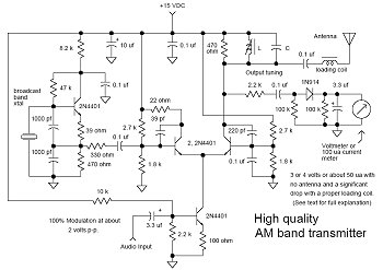
In many discussions of LPAM transmitter design, references to "the Wenzel circuit" or "the Wenzel transmitter" are common. These terms refer to a clever transmitter design that became popular in the mid-1990s and early 2000s for those interested in...
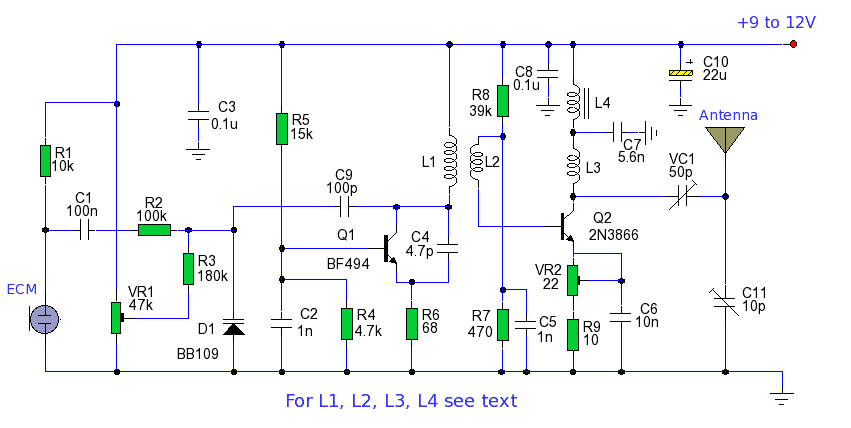
The power output of many transmitter circuits is low due to the absence of power amplifier stages. The transmitter circuit presented here includes an additional RF power amplifier stage after the oscillator stage, which elevates the power output to...
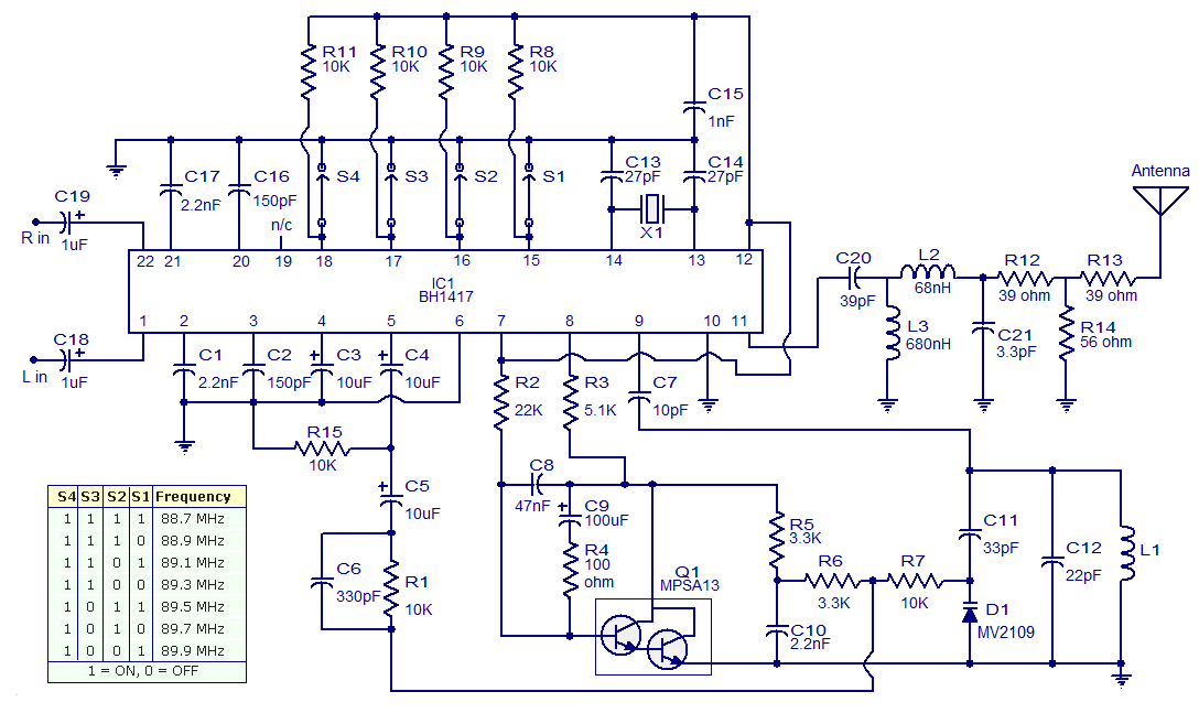
The circuit presented is a simple stereo FM transmitter capable of transmitting high-quality signals over a range of 70 feet. It utilizes the BH1417 PLL Stereo Transmitter IC from Rhom, which features distinct sections for audio processing of the...
The circuit in Figure 2 shows a 16-channel, AMI-encoded RF transmitter for data rates as high as 28.8 kbps. The circuit operates in the unlicensed (FCC Part 15) 902- to 928-MHz industrial, scientific, and medical (ISM) band and is...

One of the key challenges in the design of 4- to 20-mA current transmitters is the voltage-to-current conversion stage. Conventional transmitters use multiple op amps and transistors to perform the conversion function. These approaches have been around for a...