
Long Range FM Transmitter

The transmitter circuit design incorporates several critical components and configurations to ensure efficient operation and reliable performance. The choice of transistors T1 (BF494) and T2 (2N3866) is significant due to their suitability for VHF applications, offering low noise and high gain characteristics. The use of a varicap diode allows for fine-tuning of the oscillator frequency, which is essential for achieving the desired modulation and signal clarity.
The power amplifier stage, formed by transistor T2, is designed to handle the increased power output without distortion. The specified power output range of 200-250 milliwatts is sufficient for short-range communication, making this circuit ideal for hobbyists and educational projects. The inclusion of a heat sink for transistor T2 is crucial, as it dissipates heat generated during operation, maintaining performance stability and preventing thermal overload.
The circuit layout should be carefully implemented on a glass epoxy board to minimize parasitic capacitance and ensure signal integrity. The aluminum casing not only provides physical protection but also serves as an electromagnetic shield, reducing interference from external sources. The use of a 50-ohm antenna is critical for impedance matching, which maximizes power transfer and minimizes signal reflection.
Adjustments via potentiometers VR1 and VR2 allow users to customize the transmitter’s frequency and output power, respectively. The trimmers VC1 and VC2 are essential for fine-tuning the circuit to achieve optimal transmission conditions. Powering the circuit with a 12V rechargeable battery pack ensures portability and convenience while maintaining a stable voltage supply.
Overall, this transmitter circuit presents a practical solution for low-power VHF transmission, suitable for various applications in the field of electronics and communications. Care should be taken to adhere to legal regulations regarding transmission frequencies and power levels to avoid interference with licensed services.The power output of many transmitter circuits are very low because no power amplifier stages are incorporated. The transmitter circuit described here has an extra RF power amplifier stage, after the oscillator stage, to raise the power output to 200-250 milliwatts.
With a good matching 50-ohm ground plane antenna or multi-element Yagi antenna, thi s transmitter can provide reasonably good signal strength up to a distance of about 2 kilometres. The circuit built around transistor T1 (BF494) is a basic low-power variable-frequency VHF oscillator. A varicap diode circuit is included to change the frequency of the transmitter and to provide frequency modulation by audio signals.
The output of the oscillator is about 50 milliwatts. Transistor T2 (2N3866) forms a VHF-class A power amplifier. It boosts the oscillator signal power four to five times. Thus, 200-250 milliwatts of power is generated at the collector of transistor T2. For better results, assemble the circuit on a good-quality glass epoxy board and house the transmitter inside an aluminium case. Shield the oscillator stage using an aluminium sheet. Coil winding details are given below: Potentiometer VR1 is used to vary the fundamental frequency whereas potentiometer VR2 is used as power control.
For hum-free operation, operate the transmitter on a 12V rechargeable battery pack of 10 x 1. 2-volt Ni-Cd cells. Transistor T2 must be mounted on a heat sink. Do not switch on the transmitter without a matching antenna. Adjust both trimmers (VC1 and VC2) for maximum transmission power. Adjust potentiometer VR1 to set the fundamental frequency near 100 MHz. WARNING: Transmitting on the UK Commercial FM band is also illegal in the UK, please see the general disclaimer. This circuit is shown for educational purposes only. 🔗 External reference
Related Circuits
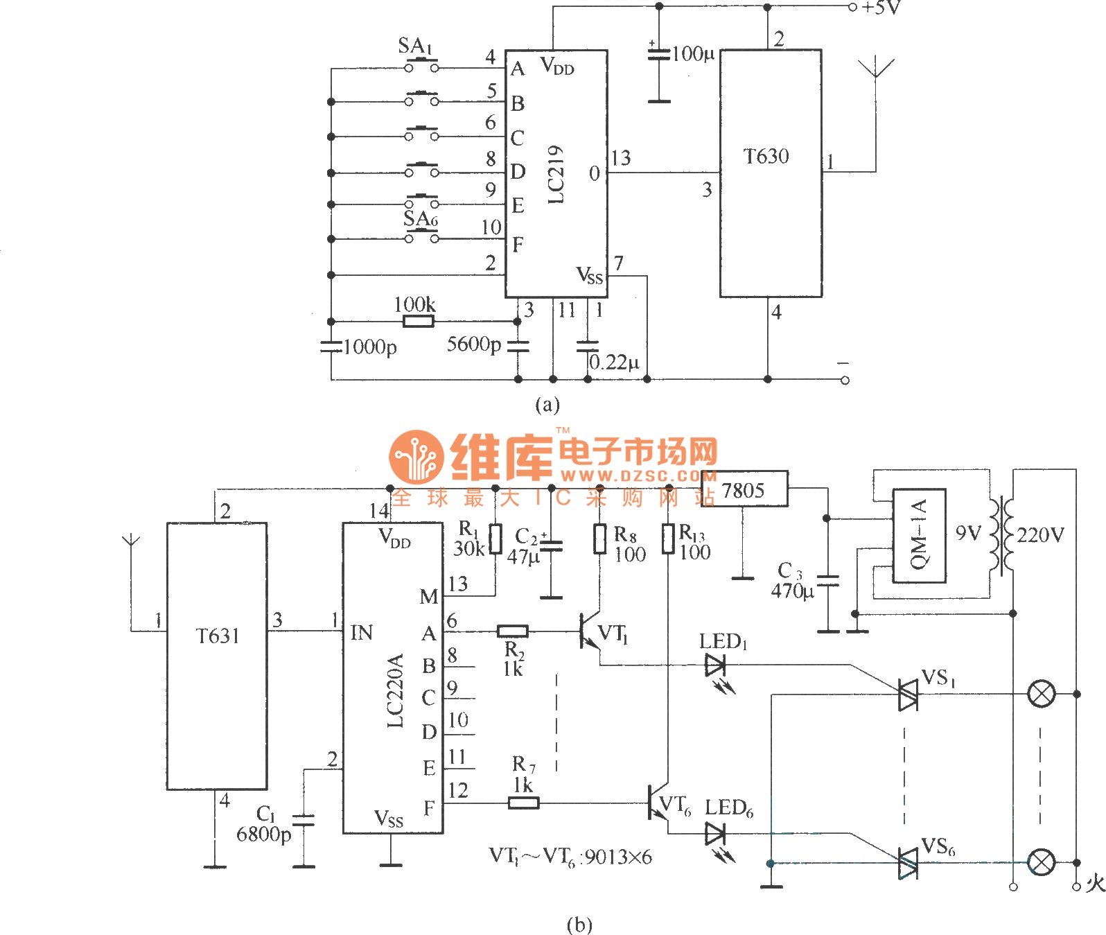
The circuit utilizes the long-wave wireless transceiver T630/T631 to manage a 6-channel load. It is characterized by low power consumption, high resistance to interference, and a simple structure. The circuit design incorporates the T630/T631 transceiver, which operates in the long-wave...
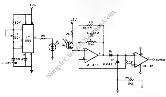
The infrared transmitter and receiver circuit depicted in the schematic diagram can function as a remote control. The transmitter operates as an oscillator circuit, with the frequency adjustable via the R1 potentiometer (or trimmer pot). This oscillation ensures that...
User Agreement & Disclaimer Disclaimer All files are found using legitimate search engine techniques. This site does not and will not condone hacking into sites to create the links it lists. It is assumed that all links found on...

In the 556 timer, the timing is determined by the charging rate of the external capacitor. For prolonged time delays, capacitors with extremely low leakage are necessary, which can be costly. The practicality of the components involved restricts the...
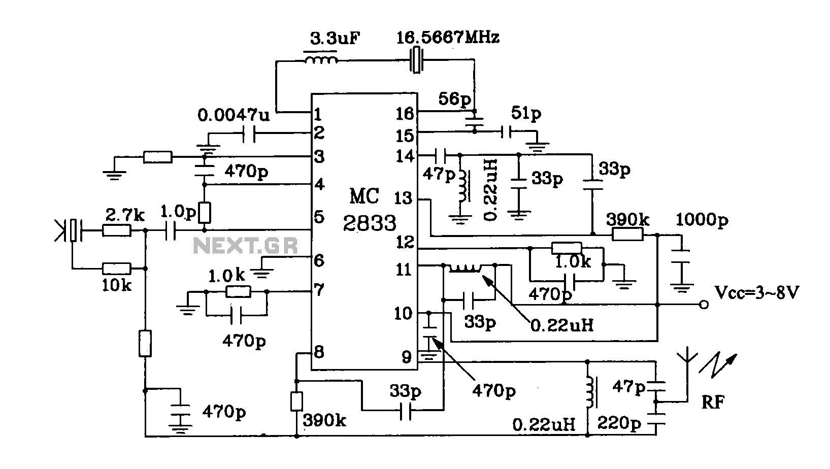
The MC2833 MC2831 radio transmitter dedicated circuit has been enhanced. This circuit is a typical application for radio transmitters, generating a high-frequency signal of 49.7 MHz that is transmitted through the antenna. The MC2833 and MC2831 integrated circuits are designed...
Construct a low-power FM transmitter using surface-mount devices (SMD) that can be received by a standard FM radio. Soldering surface-mounted devices is relatively straightforward. Many small FM transmitter designs exist, but they often have issues. Firstly, an audio amplifier...