
4W Fluorescent lamp driver
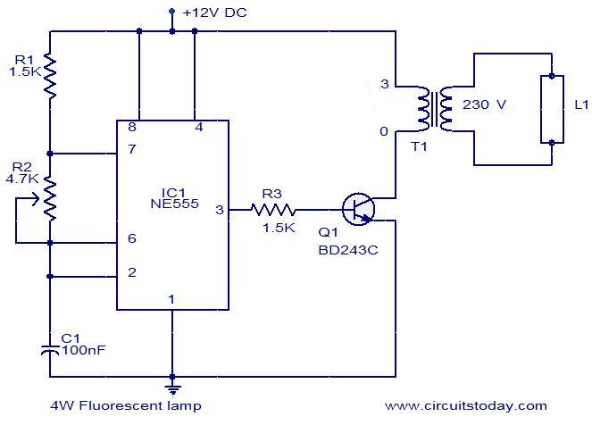
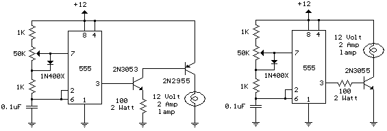
This circuit employs a NE555 timer IC configured as an astable multivibrator to generate a square wave output, which is essential for driving the fluorescent lamp. The frequency of oscillation can be adjusted by varying the resistors and capacitors connected to the NE555, allowing for fine-tuning of the output pulses. The transistor Q1 serves as an amplifier to boost the output from the NE555, supplying sufficient current to the transformer.
The transformer is a critical component, designed to step up the voltage from the collector of Q1 to approximately 1kV, which is necessary for igniting and sustaining the discharge in the fluorescent lamp. The design must consider the transformer’s core material and winding configuration to optimize performance, especially under the influence of the DC component present in the circuit.
Setting R2 to achieve a collector current of 300mA is crucial for maintaining the longevity of the fluorescent lamp. This current setting ensures that the lamp operates efficiently without excessive wear on the cathodes. The gradual degradation of the cathode coating can lead to reduced performance and lifespan, which is a common issue in fluorescent lamps subjected to non-ideal operating conditions.
In terms of efficiency, the circuit's reliance on a mains transformer is a significant drawback. Operating outside the intended frequency range can lead to core saturation, further diminishing the efficiency of power transfer to the lamp. Consequently, the lamp may not achieve its rated power output of 4W, resulting in lower brightness levels. The use of a push-pull converter with a ferrite transformer is recommended for improved efficiency and brightness. This approach allows for high-frequency operation, which is more suitable for low-voltage applications, and includes filament windings that preheat the cathodes, enhancing the startup performance of the fluorescent tube.
Overall, this circuit represents a basic implementation for driving a fluorescent lamp from a low-voltage supply, with considerations for longevity and efficiency that can be improved through alternative designs.This is a simple 4 W fluorescent lamp driver circuit that can be operated from a 12 V supply. The first part of the circuit includes a NE555 timer IC wired as an astable multivibrator. The output pulses from the IC are amplified by the transistor Q1. The transformer steps up the collector voltage to around 1KVto drive the fluorescent lamp. Before usi ng the circuit, set the R2 at full resistance and switch on the supply, now adjust R2 so that the collector current is 300mA (use a multimeter) and this is the optimum setting for the lamp. Operating the lamp in this setting will give a better life. First, the tube is being started with cold cathodes. Tube life will be shortened as the cathode coating is gradually stripped. This isn`t just a feature of this circuit, but all those cheap battery operated torches having tubes with blackened ends.
Incidentally, as there is a DC component present in the tube supply because of the single ended drive to the transformer, one end of the tube will wear out before the other. Because of the low efficiency of using a mains transformer (operating outside intended frequency range and with the interleaved core laminations saturating because of the DC component), the tube will not receive full 4W of power.
Besides, 300mA @ 12V is only 3. 6W. Therefore, it will not be as bright as one operated from the mains. A push pull converter, running at high frequency, using a ferrite transformer, and having filament windings to warm to cathodes is the best way to operate fluorescent tubes from low voltage DC. 🔗 External reference
Related Circuits
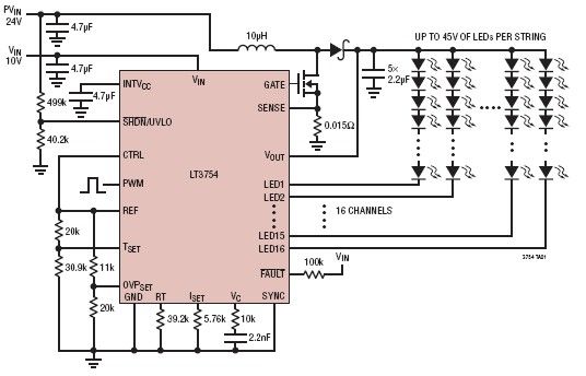
The LT3754 is a 16-channel LED driver featuring a step-up DC-DC controller developed by Linear Technology. It is designed to drive LEDs with a voltage of up to 45V. Each channel of the LT3754 LED driver is equipped with...
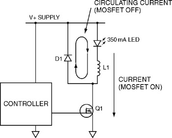
The first switching LED driver to be examined is the buck converter. The buck converter is the simplest type of switching driver and serves as a step-down converter for applications where the load voltage is typically no more than...
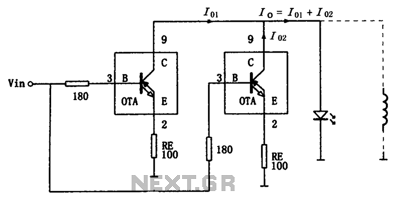
The high-speed parallel current drive circuit utilizes the OPA660 operational transconductance amplifier (OTA). An input signal, Vin, is connected to a 180-ohm resistor equivalent device at the base (pin 3) of the OPA660. The collector (pin 8) is directly...
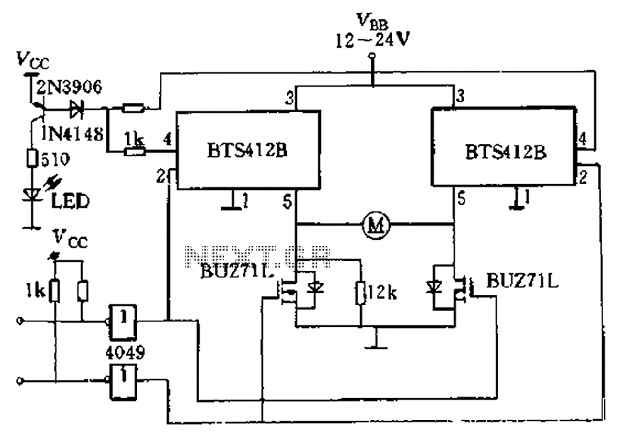
The BTS412B functions as two high-side power MOSFET switches, while two BU271L (50V, Zhang 1n) serve as low-side switches, forming a bi-directional H-bridge DC motor drive circuit. This configuration is designed for electrical automatic door systems, capable of handling...
The schematic diagram illustrates a 12 Volt Car Lamp Dimmer Circuit Design utilizing a 555 Timer. This circuit can be employed to dim a standard 25-watt lamp. The 12 Volt Car Lamp Dimmer Circuit utilizes a 555 Timer in astable...
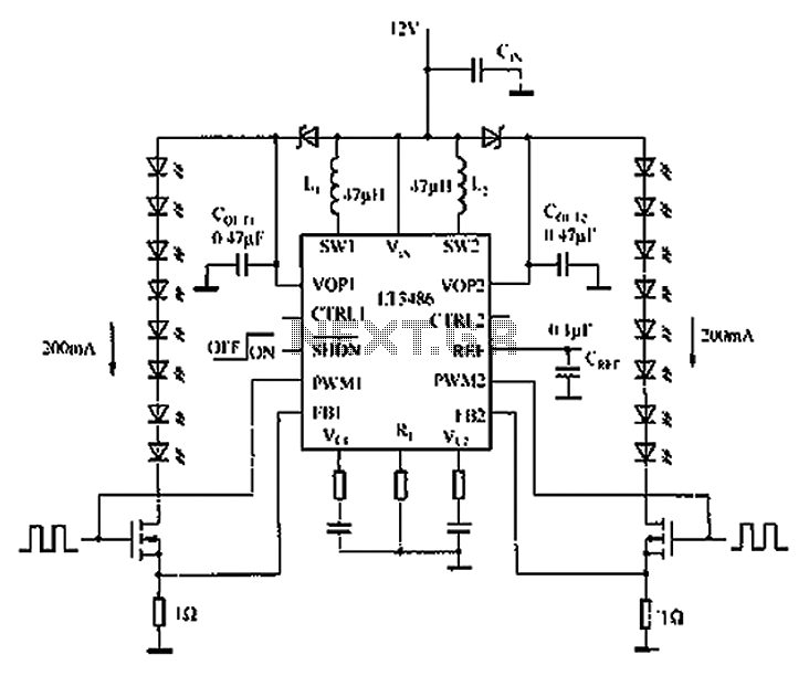
The automotive LED driver circuit diagram utilizes the LT3486. The LED is employed in the car's central high-mounted stop lamp (CHMSL), providing advantages such as faster achievement of the set brightness, higher efficiency, longer lifespan, and simplified design and...