
Parallel high-speed current driver circuit diagram OPA660

The high-speed parallel current drive circuit is designed for applications that require precise control of output current while maintaining high-speed performance. The OPA660 OTA is specifically chosen for its ability to deliver significant output current, making it suitable for driving various loads, including capacitive and resistive components. The input signal, Vin, is effectively conditioned by the 180-ohm resistor, which mitigates the risk of self-oscillation that could compromise circuit stability. This resistor also plays a crucial role in shaping the frequency response of the amplifier, ensuring that the circuit operates efficiently across the desired frequency range.
In parallel configurations, the OPA660s work cohesively to provide the necessary current without exceeding individual device limits. This approach not only enhances the overall output capability but also ensures redundancy, as the failure of one OTA does not significantly impact the performance of the entire circuit. The inclusion of the negative feedback resistor, RE, contributes to the circuit's robustness by stabilizing the gain and improving linearity. However, it is essential to select the appropriate value for RE, as it directly influences the transconductance of the OTA, thereby affecting the output current. The careful design of this circuit allows for versatility in applications, from audio amplification to signal conditioning in communication systems, where high-speed and high-current drive capabilities are paramount. As shown for the high-speed parallel current drive circuit. Input signal Vin have been added 180 resistor equivalent device OPA660 special OTA transistor base B (pin 3), the co llectors C (pin 8) connected directly, and connected with the load, while providing current to the load, thus the current flowing through a single OTA twice the load, because the OTA OPA660 maximum output current of 15mA, while the parallel circuit provides a maximum output current up to 30mA. When you need more current, multiple OPA660 op amps in parallel, in order to obtain the desired load current.
Input (B pole) 180 external resistor having a limiting effect, while preventing self-oscillation occurs amplifier and reduce the phenomenon peaking frequency characteristics. Connected to the emitter of the negative feedback resistor RE (tens of ohms to several hundred ohms) can increase the number of dynamic index linear amplifier input impedance and stability, but the OTA transconductance will decline, it can be seen, RE appropriately changing the resistance can adjust the size of the output current.
Related Circuits
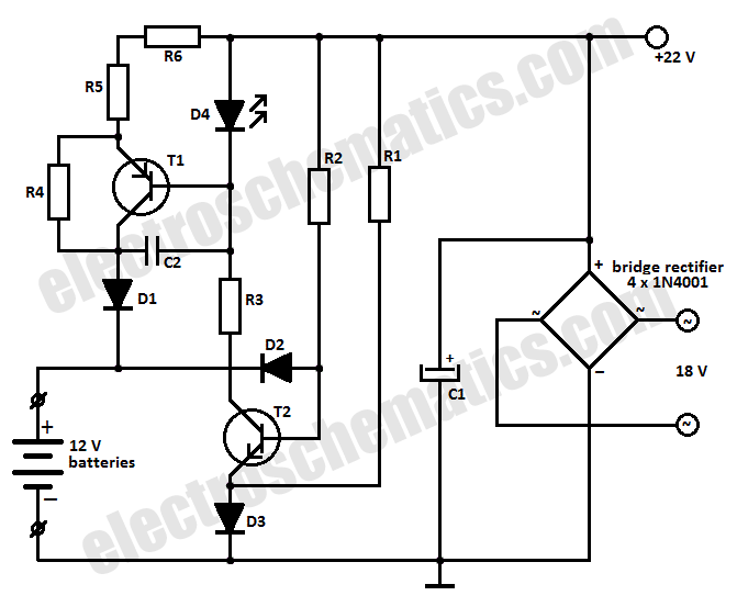
This battery charger circuit is designed to charge one or more batteries with a total nominal voltage of 12 V, which accommodates either ten NiCd batteries or six 2 V lead-acid batteries. The battery charger circuit operates by utilizing a...
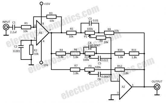
This three-band equalizer circuit functions as an active filter network for bass, mid, and high audio frequencies. It is built around the LM833 operational amplifier from National Semiconductors. The output of this three-way graphic equalizer is configured to be...
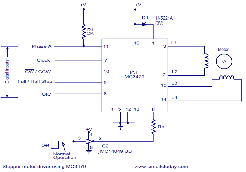
The circuit diagram presented is for a stepper motor driver utilizing the MC3479 integrated circuit from Motorola. The MC3479 is specifically engineered for driving a two-phase stepper motor in bipolar mode and is available in both standard DIP and...
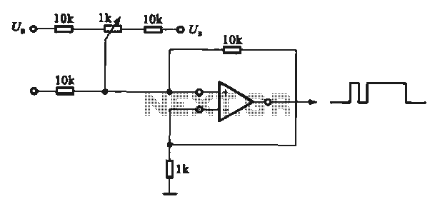
This circuit demonstrates the application of various types of pulse signal generating circuits using operational amplifiers. The circuit utilizes operational amplifiers (op-amps) to create different forms of pulse signals, which are essential in many electronic applications, including waveform generation, timing...
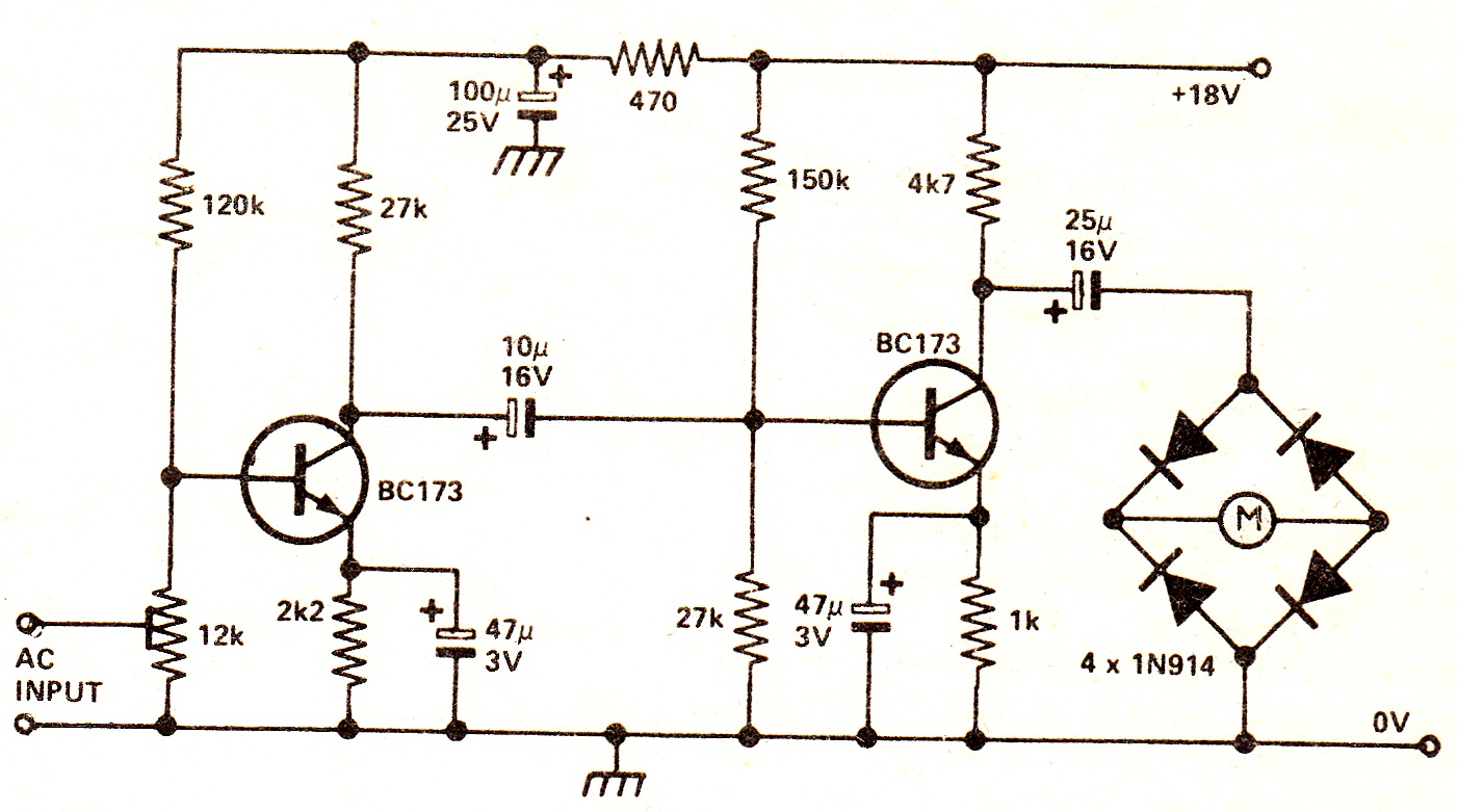
The circuit illustrates a two-stage voltage amplifier that drives a recording level meter. An AC signal input is amplified and rectified, with the resulting DC voltage displayed on the meter. This circuit is compatible with tape recorders or audio...
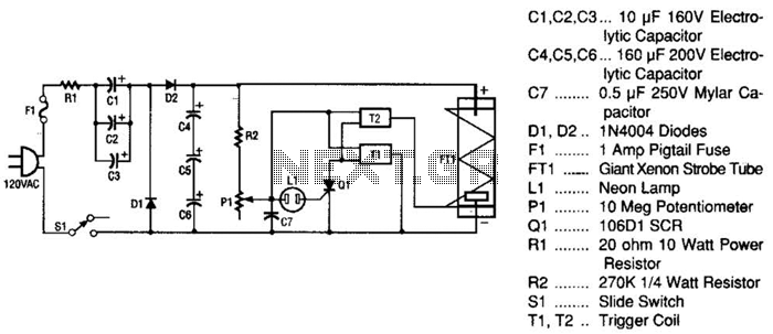
This strobe light operates from standard 120-Vac power. Resistor R1 limits the amount of current applied to the voltage doubler stage, which consists of capacitors C1, C2, C3, and diodes D1, D2, along with capacitors C4, C5, and C6....