
5-12V DC regulated Power Supply

The described circuit is a basic linear power supply utilizing the LM78XX series of voltage regulators, which are widely used for providing stable output voltages. The power supply design features a transformer, rectifier, filter capacitors, and the voltage regulator itself, creating a reliable source of DC voltage.
The transformer is a critical component that steps down the AC mains voltage to a lower AC voltage suitable for the desired output. For output voltages ranging from 5V to 12V, an 18VAC transformer is appropriate. This voltage is selected to ensure that after rectification and smoothing, the voltage remains within the input range of the LM78XX regulators. For higher output voltages, specifically between 15V and 24V, a 30VAC transformer is recommended, allowing for adequate headroom after rectification.
The rectification stage typically employs a bridge rectifier configuration, which converts the AC voltage from the transformer into pulsating DC voltage. The output of the rectifier is then smoothed using filter capacitors. The first capacitor in the circuit plays a vital role in maintaining the output voltage stability and is generally sized at 2000µF for every amp of current drawn by the load. This ensures that the voltage does not drop significantly during load variations.
Following the filtering capacitors, the LM78XX voltage regulator is connected. This device regulates the output voltage to the desired level while providing short circuit and thermal protection. The specific model of the LM78XX series used will depend on the required output voltage, which is determined by the design specifications of the application.
Additional bypass capacitors may be placed at the input and output of the voltage regulator to further enhance stability and transient response. These capacitors help filter out high-frequency noise and provide a more stable output voltage under varying load conditions.
Overall, this power supply circuit is straightforward yet effective, making it suitable for various electronic applications requiring a stable DC voltage source. Proper component selection, especially for the transformer and capacitors, is essential to ensure optimal performance and reliability.I didn't realize till the other day that I have never shown a circuit for a standard power supply. Shown below is a supply that will use any of the LM78XX series of voltage regulators. The transformer in the circuit will vary depending on which regulator you use. For voltages from 5 to 12 use a transformer with output of 18vac. With voltages from 15 to 24 use a transformer of 30vac. The first capacitor in the circuit may need to vary if you are supplying more current to the load. Typically it will be 2000uf for every amp of current. 🔗 External reference
Related Circuits
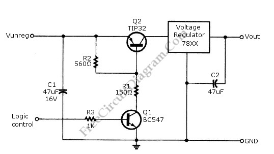
Logic power control of an analog regulator can be useful in applications where a digital circuit or controller needs to manage a power source, such as in EEPROM programmers or other power control systems. This circuit provides ON-OFF control...
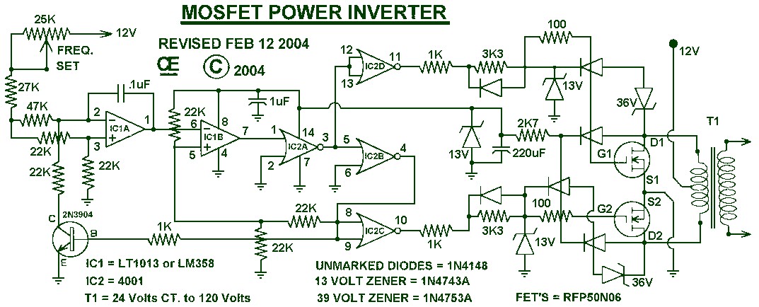
1000W Power Inverter circuit diagram: This is a power inverter circuit based on the MOSFET RFP50N06. The inverter is capable of handling loads up to 1000W, depending on the specifications of the transformer used. The RFP50N06 MOSFETs are rated...
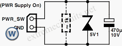
An additional push-button switch is typically required for the ATX Power Switch/Soft Power Switch signal; however, this simple circuit eliminates that need. The design is effective and has undergone extensive testing. A zener diode is included to protect against...
The following circuit illustrates an Automatic Room Power Control Circuit Diagram. This circuit is based on the NE555 integrated circuit (IC). Features include the use of two Light Dependent Resistors (LDRs). The Automatic Room Power Control Circuit utilizes an NE555...
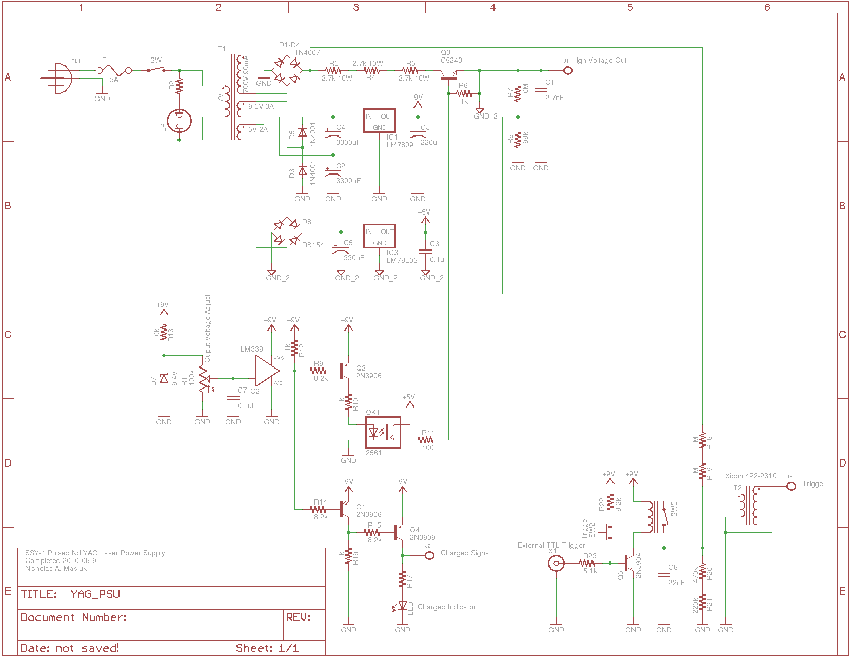
The SSY-1 is a compact pulsed Nd:YAG laser that was initially utilized as part of the laser rangefinder in the M1 Abrams tank. The laser head and PFN-1 pulse forming network, which includes a flashlamp capacitor, inductor, and diode,...
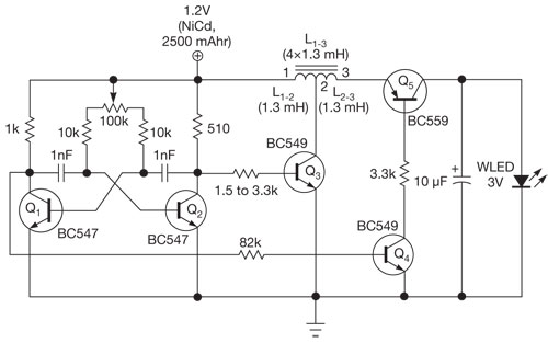
This single white LED torch can be housed in an empty glue stick tube and has a long rechargeable battery life. The proposed circuit design features a compact LED torch that utilizes a single white LED as the primary light...