
Voice music outlet circuit diagram SK- made

The described circuit integrates several key components, each serving a distinct function to achieve the desired operational characteristics.
1. **Acoustic Sensor**: This component detects sound waves and converts them into electrical signals. It is essential for capturing audio input, which will be processed by the subsequent circuits.
2. **SK Voice Circuit**: This circuit is designed to process the signals received from the acoustic sensor. It typically includes amplification and filtering stages to enhance the quality of the audio signal before it is passed on to the relay control circuit.
3. **Relay Control Circuit**: The relay control circuit acts as a switch that can be activated by the processed audio signals. When the acoustic sensor detects sound and the SK voice circuit processes it, the relay may be triggered to perform a specific action, such as turning on a device or activating another circuit.
4. **Vocal Music Circuit**: This circuit may serve to generate vocal music or sound effects based on the input received from the SK voice circuit. It can include various sound synthesis techniques to produce the desired audio output.
5. **AC Buck Rectifier Circuit**: This component is responsible for converting alternating current (AC) to direct current (DC). The buck rectifier ensures that the power supply is stable and suitable for the operation of the circuit components, particularly the relay and audio circuits.
The integration of these components allows for a versatile circuit capable of responding to acoustic signals and generating appropriate outputs, making it suitable for applications such as sound-activated devices, alarms, or interactive sound systems. Proper attention to the design and layout of the circuit will ensure optimal performance and reliability. Circuit As shown, it comprises an acoustic sensor, SK- voice circuit, relay control circuit, vocal music circuit and the AC buck rectifier circuit. BM acoustic/electric transdu cer.
Related Circuits

The circuit illustrated below represents a simple thermometer circuit based on the LM335 temperature sensor. This circuit comprises two main components: the LM335 sensor and its adjustment circuitry. The output from the LM335 generates a voltage of 10 millivolts...
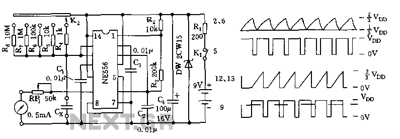
The tester comprises a dual time base circuit using a 556 timer and various RC components. The right side of the circuit features the 556 timer (556 1/2) along with resistors R2, R3, capacitors C2, C3, and additional components...
Due to the low coupling coefficient, the primary self-inductance tends to short out the driving signal. However, utilizing a series/parallel set of capacitors for energy coupling increases the input impedance at resonance, thereby achieving good power transfer efficiency. The...
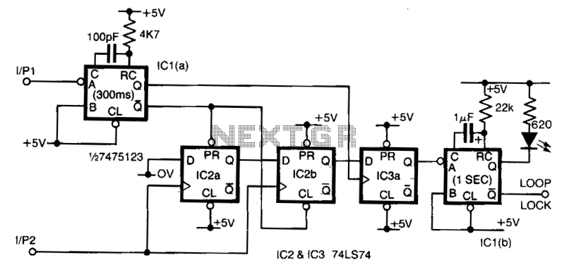
Input 1 functions as a gating period, during which a single rising edge on input 2 produces a logic 1 output. Any other input that indicates non-identical frequencies results in a logic 0 output. IC1a converts input 1 into...
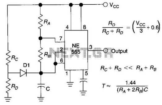
Using Rl, R7, and D1 to preset CI to one third of the supply voltage. This circuit avoids a longer first cycle period than subsequent cycles. The circuit described involves the use of resistors Rl and R7 along with diode...
The LED flasher circuits below operate on a single 1.5 volt battery. The circuit on the upper right uses the popular LM3909 LED flasher IC and requires only a timing capacitor and LED. The top left circuit, designed by...