Sensitive FM Radio Tuner Circuit
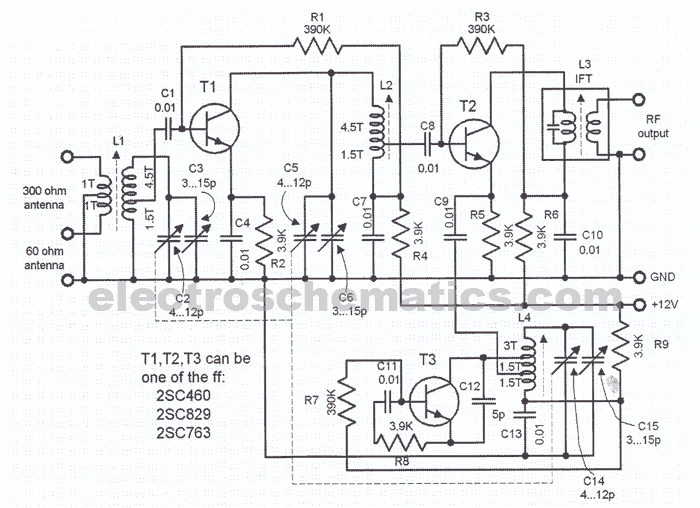
This sensitive FM radio tuner is an ideal circuit for hobbyists who wish to construct their own tuners rather than purchasing a pre-assembled product.
The FM radio tuner circuit is designed to receive frequency modulation signals, providing a clear and stable audio output. The core components typically include an RF amplifier, a mixer, a local oscillator, and a demodulator. The RF amplifier boosts the incoming radio frequency signals, enhancing the overall sensitivity of the tuner.
The mixer combines the amplified RF signal with a signal from the local oscillator, which is usually generated by a variable capacitor and an inductor, allowing the circuit to tune into different frequencies. The output of the mixer is then fed into the demodulator, which extracts the audio information from the modulated carrier wave.
Additional components that may be included in the circuit are filters for signal conditioning, such as bandpass filters, which help eliminate unwanted frequencies and improve sound quality. A microcontroller or a simple analog circuit can also be used to provide tuning controls, allowing users to select their desired frequency easily.
Power supply considerations are crucial, as the circuit typically operates on low voltage to ensure safety and compatibility with battery-operated devices. The design can be further enhanced with the inclusion of an audio amplifier to drive speakers or headphones, providing a complete FM listening experience.
Overall, this FM radio tuner circuit offers a rewarding project for electronics enthusiasts, combining practical skills with the satisfaction of building a functional device from scratch.This sensitive FM radio tuner is the right circuit for hobbyists who want to build their own tuners instead of buying a ""plug-n-play"" finished product. The.. 🔗 External reference

