
5 mA S METER

The circuit operates by amplifying low-level signals to drive a 5 mA meter movement effectively. The two-stage voltage amplifier configuration, consisting of Q1 and Q2, enhances the input signal while maintaining linearity and stability. The use of transistors allows for efficient amplification with minimal distortion, which is crucial for accurate meter readings.
Transistor Q3 acts as an emitter follower, providing high input impedance and low output impedance. This characteristic is essential for impedance matching, ensuring that the circuit can interface effectively with various signal sources without loading them down. The specified input voltage levels of 25-30 mV P-P for an S-9 reading and 50-60 mV P-P for full scale indicate the range of input signals that the circuit can accurately process.
The frequency response of 500 Hz to 10 kHz indicates the operational bandwidth of the circuit, making it suitable for audio frequency applications. This range is particularly relevant for applications in radio communications and audio signal processing, where maintaining fidelity over this frequency range is vital for effective signal representation.
Overall, the design demonstrates a well-thought-out approach to signal amplification and impedance matching, ensuring reliable performance in practical applications. The reference to M.A. Chapman's work further underscores the circuit's credibility and relevance within the field of electronics, particularly in the context of solid-state meters used in amateur radio.Circuit designed for 5-mA meter movement uses two-stage voltage ampilfer Q1-Q2 with emitter-follower output Q3 serving as impedance-matching stage AF input for S-9 reading is 25-30mV P-P and forfull scale is 50-60mV P-P Frequency response is 500 Hz to 10 kHz-M A Chapma, Solid-State S-Me-ters, Ham Radio March 1975 p 20-23 🔗 External reference
Related Circuits
This circuit is a low-cost frequency meter that operates within the range of 1 Hz to 1 MHz. It utilizes an IC1 Schmitt trigger to regulate the input signal, adjusting it to a suitable level for IC2, IC3, and...
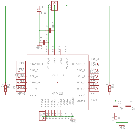
Establish communication between the microcontroller unit (MCU) and the accelerometer using either I2C or SPI protocols. It has been noted that shorting the phase-locked loop (PLL) filter input in the device does not affect the readings from the gyroscope...
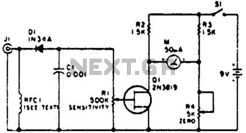
This circuit employs a FET as a DC amplifier within a bridge configuration. Resistor R4 is adjusted for meter nulling with switch J1 short-circuited. Any surplus 50-mA meter can be utilized in this circuit. RFC1 represents a suitable RF...

The ESR Meter is essentially an AC Ohmmeter equipped with specialized scales and protective circuitry. It provides continuous readings of series resistance in electrolytic capacitors. Operating at 100 kHz, it maintains the capacitive reactance factor close to zero. The...
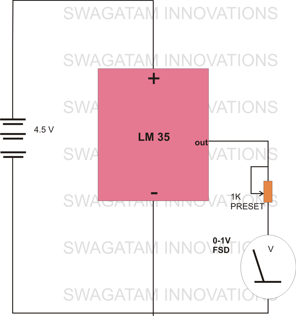
The circuit diagram provided illustrates a straightforward setup. There is no requirement for complex circuitry; simply connect a 0-1 V full-scale deflection (FSD) moving coil meter across the designated pins of the integrated circuit (IC). Adjust the potentiometer as...
A vibration meter circuit depicted in the schematic diagram utilizes the LM3915 as the primary active component. This vibration meter employs a piezoelectric sensor. The vibration meter circuit is designed to measure and display vibration levels through a visual output....