
5-Range Linear-Scale Ohmmeter

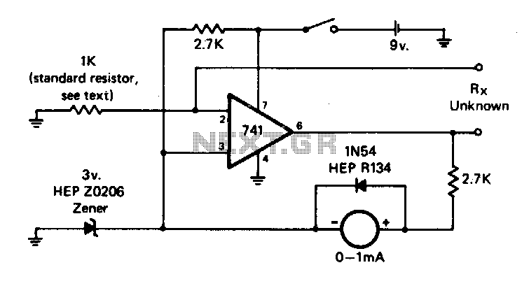
In this electronic circuit, Rx serves as a variable resistor that is strategically positioned within the feedback loop of an operational amplifier, designated as IC1. The feedback configuration allows for precise control and measurement of the output voltage in relation to the input current flowing through Rx. The reference voltage generator, comprising Q1 (a transistor) and D1 (a diode), establishes a stable reference current that is critical for the circuit's operation.
Resistors R5 through R9 are employed to create a series of selectable resistance values, enabling the circuit to adapt to various measurement scenarios. The resistance values are selected through a switching mechanism, which can be either manual or automated, to correspond with the desired measurement range. The total resistance in the feedback loop, denoted as R^, is calculated based on the selected resistor from the series (Rs through R9), ensuring that the circuit can accommodate a range of input signals.
The output of the circuit is connected to a meter, which provides a direct reading of the current flowing through Rx. This output is linearly related to the value of Rx, allowing for straightforward interpretation of the measurement. As Rx changes, the feedback path adjusts the gain of the operational amplifier, thereby affecting the output voltage in a predictable manner. This design is particularly useful in applications requiring precise current measurement and control, such as in sensor interfacing or calibration processes. The linear relationship between the selected resistance and the meter reading allows for easy scaling and interpretation of results, making the circuit versatile for various electronic applications. Rx is inserted in the feedback path of IC1. A known reference current is selected from reference voltage gene rator Ql, Dl, and R5 through R9. A meter reading will be produced: where R^=Rs through R9, as selected. This corresponds linearly to the value of Rx.
Related Circuits
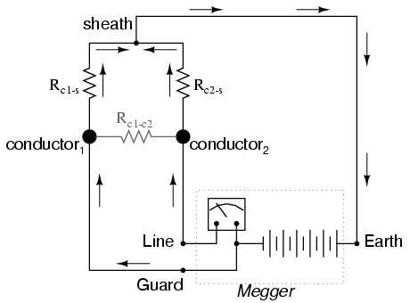
Most ohmmeters of the design shown in the previous section utilize a battery of relatively low voltage, usually nine volts or less. This is adequate for measuring resistances under several mega-ohms (MΩ), but when extremely high resistances need to...
This circuit features a linear reading scale, does not require calibration, and does not necessitate zero adjustment. It can be configured for multiple ranges by incorporating different standard resistors. The circuit operates on the principle of linear response, ensuring that...

A single preset resistor is utilized across all measurement ranges, which simplifies the setup process. Diode clamping is incorporated to protect the meter from damage if the unknown resistor exceeds the selected range. When the meter is assembled, a...
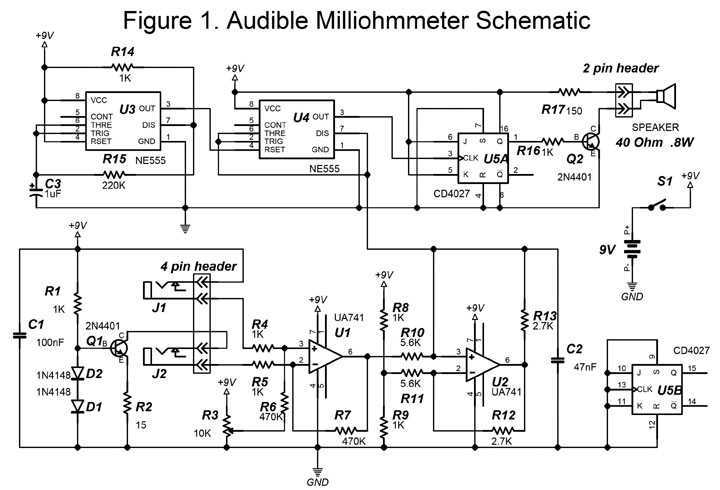
This project uses a four-point resistance measurement process also known as the Kelvin method. This procedure uses a current source to determine the value of an unidentified resistance. A constant current flows through the unknown resistance and the voltage...

The ESR Meter is essentially an AC Ohmmeter equipped with specialized scales and protective circuitry. It provides continuous readings of series resistance in electrolytic capacitors. Operating at 100 kHz, it maintains the capacitive reactance factor close to zero. The...
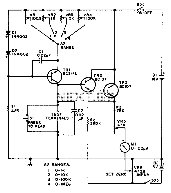
This circuit is designed to provide accurate measurement and a linear resistance scale at the high end. The circuit has four ranges. Additionally, another meter with a current range of 10 µA to 10 mA and a sensitivity of...