
Linear scale ohmmeter

The circuit is structured to deliver precise measurements across multiple resistance ranges, enhancing its utility in various applications. The four ranges facilitate the measurement of different resistance values, allowing users to select the appropriate scale based on the specific requirements of the task at hand. This feature is particularly beneficial in laboratory settings, where accurate resistance measurements are critical.
The inclusion of a second meter capable of measuring current from 10 µA to 10 mA adds versatility to the setup. This meter's high sensitivity of 10,000 ohms per volt indicates its ability to measure low currents with great accuracy, making it suitable for applications involving sensitive electronic components.
In addition to the basic functionality, the circuit may incorporate operational amplifiers to enhance measurement precision and linearity. These amplifiers can be configured to provide a stable reference voltage, improving the overall accuracy of the resistance measurements.
Furthermore, the circuit design may include a switch mechanism that allows users to easily change between the different resistance ranges. This switch can be implemented using rotary or slide switches, ensuring a user-friendly interface.
Overall, the combination of a multi-range resistance measurement circuit and a high-sensitivity current meter provides a comprehensive solution for precise electronic measurements, making it an essential tool for engineers and technicians in the field.This circuit is designed to provide accurate measurement and a linear resistance scale at the high end. The circuit has four ranges Another meter with a current range of 10 µ A to 10 mA and sensitivity of 10,000 ohms per volt is needed for setting up.
Related Circuits
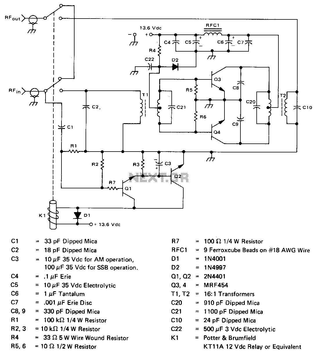
The amplifier operates across the 2-30 MHz band with a relatively flat gain response and reaches gain saturation at approximately 210 W of output power. Both input and output transformers have a 4:1 turns ratio (16:1 impedance ratio) to...
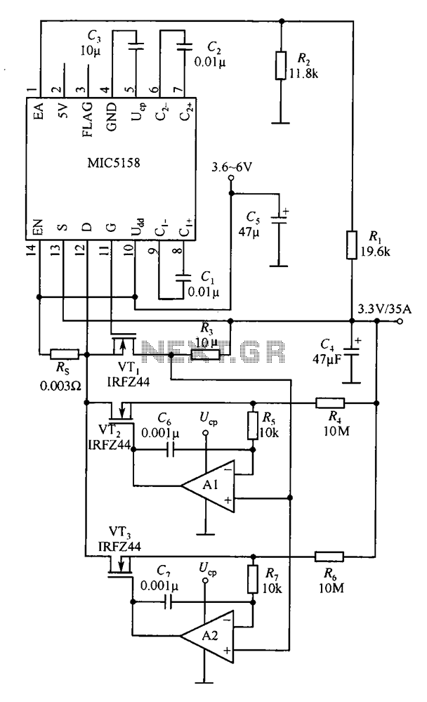
The MIC5158 is designed to manage tasks by controlling multiple external N-channel MOSFETs in parallel, which enables high current or high power output for a linear regulator circuit. This is illustrated in the accompanying figure. The operational amplifier circuit...
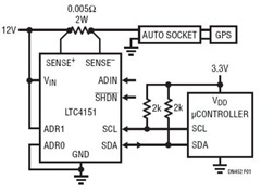
This power monitoring device accurately measures voltage and current on a positive supply rail ranging from 7V to 80V through a straightforward I2C interface, as specified in the datasheet. It is particularly suitable for automotive applications that require power...
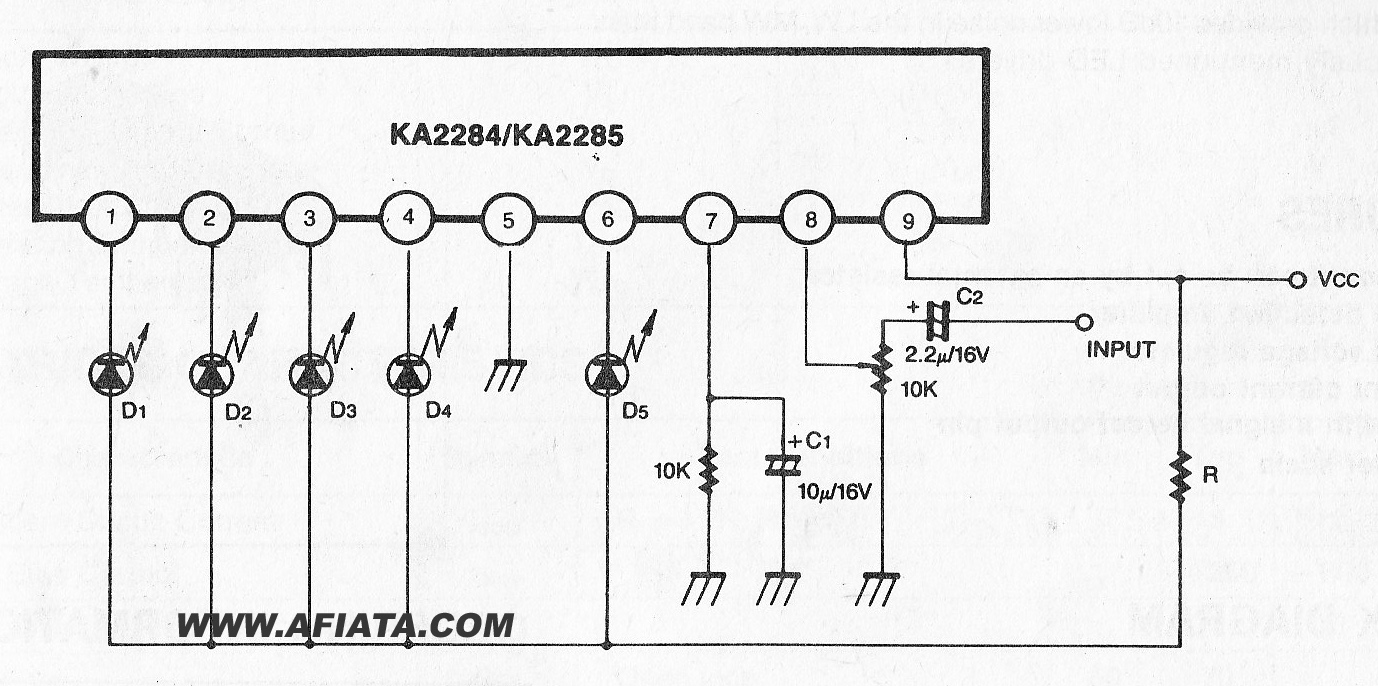
The KA2284 is a monolithic integrated circuit designed for 5-dot LED level meter drives with a built-in rectifying amplifier. It is suitable for both AC and DC level meters, such as VU meters or signal meters. The KA2284 integrated circuit...
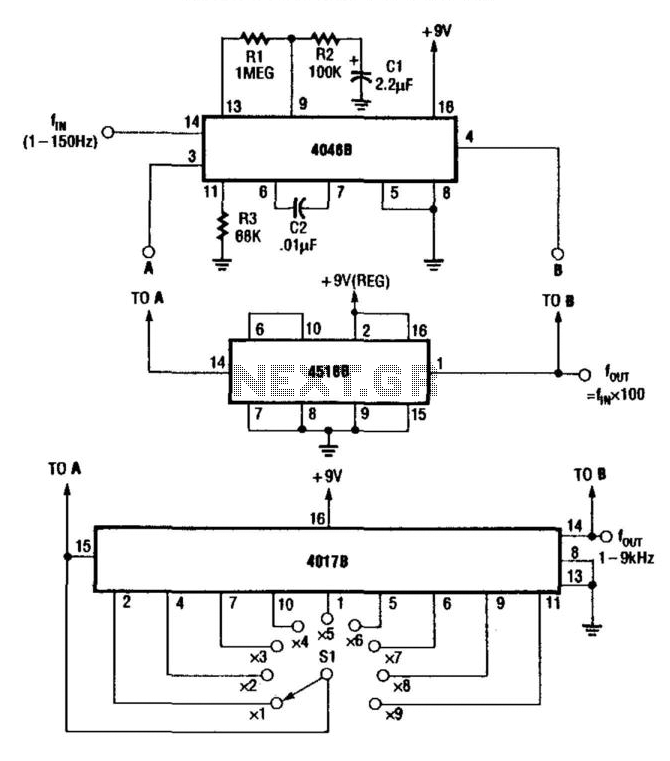
For multiplying frequencies in the 1 to 150 Hz range, this circuit utilizes a 4046B phase-locked loop (PLL) and a 100 prescaler. The output from the voltage-controlled oscillator (VCO) is phase-locked to the low-frequency input. This configuration facilitates the...

The ESR Meter is essentially an AC Ohmmeter equipped with specialized scales and protective circuitry. It provides continuous readings of series resistance in electrolytic capacitors. Operating at 100 kHz, it maintains the capacitive reactance factor close to zero. The...