
High voltage ohmmeters

The high-voltage ohmmeter operates on the principle of varying the applied voltage to assess resistance in non-linear materials effectively. The design incorporates a robust electromechanical meter movement that utilizes multiple coils to achieve stable readings. Each coil is strategically placed within a magnetic field, allowing for precise needle deflection based on the current flowing through the test leads. This configuration ensures that the device can accurately measure a wide range of resistances while accounting for the inherent variability in resistance due to changes in voltage.
The calibration of the meter is critical to maintain accuracy, especially when measuring high resistances. The design avoids the pitfalls of traditional ohmmeters that rely on a single voltage level, which can lead to misleading readings when dealing with materials that exhibit non-linear resistance characteristics. By allowing for voltage adjustments, the high-voltage ohmmeter can be tailored to the specific requirements of the measurement task at hand.
In practical applications, such a device is invaluable in fields where high-voltage insulation testing is necessary, such as in the evaluation of electrical components, insulation systems, and safety testing of electrical equipment. The ability to produce reliable resistance measurements across a range of conditions enhances the utility of this high-voltage ohmmeter, making it a crucial tool for engineers and technicians in the electrical and electronics industries.Most ohmmeters of the design shown in the previous section utilize a battery of relatively low voltage, usually nine volts or less. This is perfectly adequate for measuring resistances under several mega-ohms (M ©), but when extremely high resistances need to be measured, a 9 volt battery is insufficient for generating enough current to actuate an electromechanical
meter movement. Also, as discussed in an earlier chapter, resistance is not always a stable (linear) quantity. This is especially true of non-metals. Recall the graph of current over voltage for a small air gap (less than an inch): While this is an extreme example of nonlinear conduction, other substances exhibit similar insulating/conducting properties when exposed to high voltages. Obviously, an ohmmeter using a low-voltage battery as a source of power cannot measure resistance at the ionization potential of a gas, or at the breakdown voltage of an insulator.
If such resistance values need to be measured, nothing but a high-voltage ohmmeter will suffice. The most direct method of high-voltage resistance measurement involves simply substituting a higher voltage battery in the same basic design of ohmmeter investigated earlier: Knowing, however, that the resistance of some materials tends to change with applied voltage, it would be advantageous to be able to adjust the voltage of this ohmmeter to obtain resistance measurements under different conditions: Unfortunately, this would create a calibration problem for the meter. If the meter movement deflects full-scale with a certain amount of current through it, the full-scale range of the meter in ohms would change as the source voltage changed.
Imagine connecting a stable resistance across the test leads of this ohmmeter while varying the source voltage: as the voltage is increased, there will be more current through the meter movement, hence a greater amount of deflection. What we really need is a meter movement that will produce a consistent, stable deflection for any stable resistance value measured, regardless of the applied voltage.
The numbered, rectangular blocks in the above illustration are cross-sectional representations of wire coils. These three coils all move with the needle mechanism. There is no spring mechanism to return the needle to a set position. When the movement is unpowered, the needle will randomly "float. " The coils are electrically connected like this: With infinite resistance between the test leads (open circuit), there will be no current through coil 1, only through coils 2 and 3.
When energized, these coils try to center themselves in the gap between the two magnet poles, driving the needle fully to the right of the scale where it points to "infinity. " Any current through coil 1 (through a measured resistance connected between the test leads) tends to drive the needle to the left of scale, back to zero.
The internal resistor values of the meter movement are calibrated so that when the test leads are shorted together, the needle deflects exactly to the 0 © position. Because any variations in battery voltage will affect the torque generated by both sets of coils (coils 2 and 3, which drive the needle to the right, and coil 1, which drives the needle to the left), those variations will have no effect of the calibration of the movement.
In other words, the accuracy of this ohmmeter movement is unaffected by battery voltage: a given amount of measured resistance will produce a certain needle deflection, no matter how much or little battery voltage is present. The only effect that a variation in voltage will have on meter indication is the degree to which the measured resistance changes with applied voltage.
So, if we were to use a megger to measure the resistance of a gas-discharge lamp, it would read very high resistance (needle to the far right of the scale) for low voltages and low resistance (needle moves to the left of the s 🔗 External reference
Related Circuits
High pressure alarm with high sensitivity. It detects high-voltage electric energy from 10kV at a distance of 2m or from low-voltage mains (AC 220V) at a distance of 0.3m. The alarm device is simple to manufacture, compact, and user-friendly....
The power-supply controller features staggered voltage-output sequencing. Four voltage outputs are activated simultaneously for voltage tracking; two outputs are designated for core and I/O supplies during power-up, while the other two outputs cater to line driver supplies where tracking...
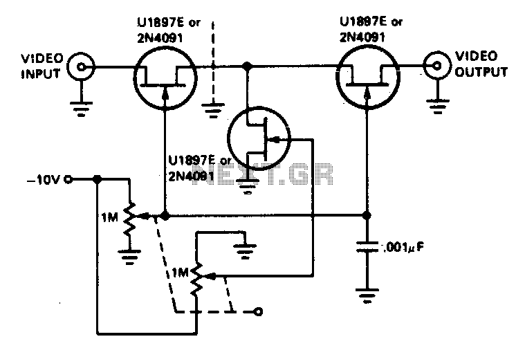
The tee attenuator offers optimal dynamic linear range attenuation of up to 100 dB, even at a frequency of 10.7 MHz with appropriate layout. The tee attenuator is a crucial component in RF and audio applications where signal integrity and...
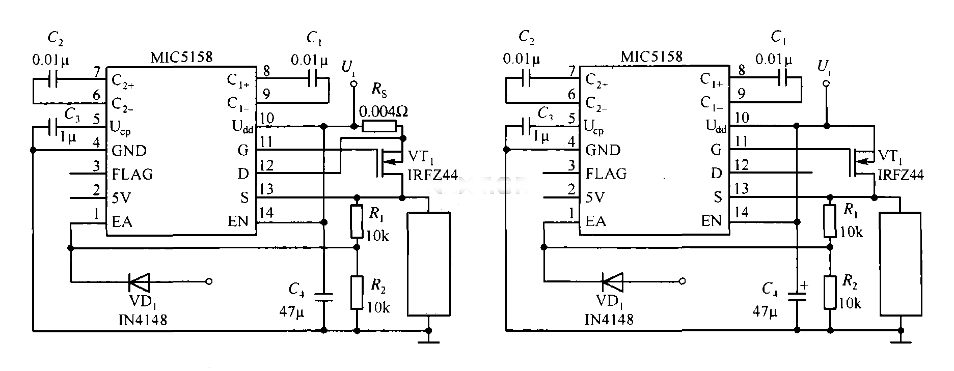
The MIC5158 is part of a high-speed switching circuit diagram that focuses on the rising edge. The MIC5158 is a precision voltage reference and high-speed switching device that is commonly utilized in various electronic applications requiring rapid signal transitions. In...
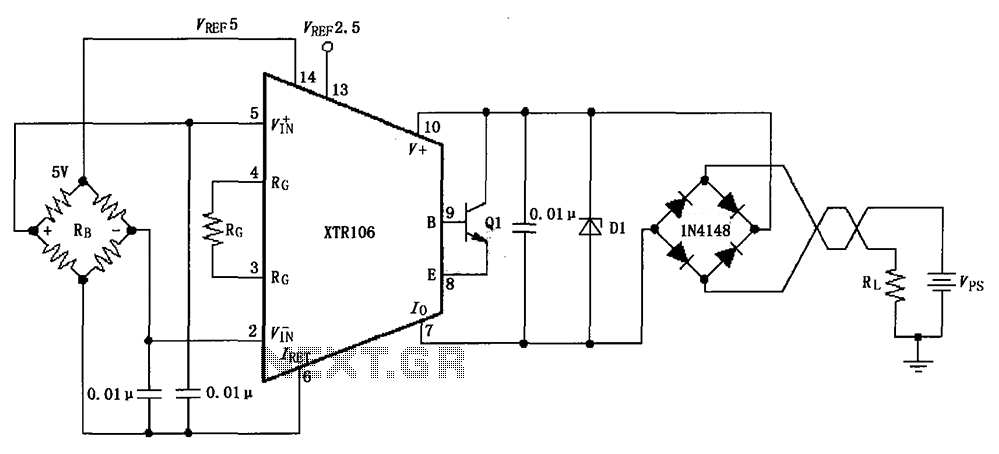
The circuit utilizes a Zener diode D1 to limit surge voltage and incorporates a four-diode rectifier bridge to prevent reverse voltage. The Zener diode D1 is rated at 36V, with optional choices being 1N4753A or 6KE39A. When the loop...
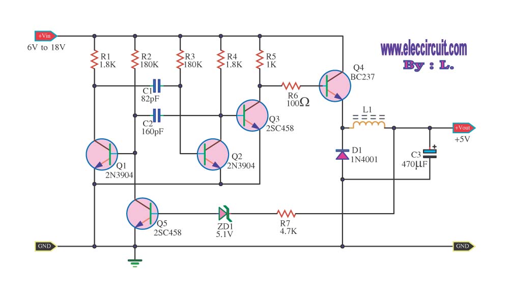
The circuit reduces voltage size or functions as a step-down voltage converter circuit, specifically a DC regulated circuit model using a switching converter. It generates the desired voltage output. The step-down voltage converter circuit, also known as a buck converter,...