
5 to 30 Minute Timers

This circuit utilizes the CMOS 7555 timer, which is essential for achieving the desired timing functionality due to its lower power consumption and higher performance characteristics compared to the standard 555 timer. The choice of a Tantalum Bead capacitor for C1 is critical, as it ensures minimal leakage current, which is vital for maintaining accurate timing intervals in low-power applications.
The timing mechanism is controlled by a resistor network, with R1 playing a pivotal role in setting the timing period. The switch S3 allows for the selection of different resistor values, effectively altering the timing duration. In position "a," the circuit is configured with an 8.2 MΩ resistor, while position "f" increases the resistance to 49.2 MΩ, significantly extending the timing interval. This flexibility permits the user to tailor the timing characteristics to specific application requirements.
The output from Pin 3 of the 7555 timer is a square wave signal that can be used to control various devices. In this design, the output is fed into transistor Q1, which serves to amplify the output current. This amplification is crucial for driving a relay, allowing the circuit to control higher power loads that exceed the output capabilities of the timer alone. The relay acts as a switch, enabling or disabling connected devices based on the timing intervals set by the circuit.
Overall, this circuit exemplifies a practical application of the CMOS 7555 timer in timing and control systems, showcasing the importance of component selection and configuration in achieving reliable performance.Simple to build, simple to make, nothing too complicated here. However you must use the CMOS type 555 timer designated the 7555, a normal 555 timer will not work here due to the resistor values. Also a low leakage type capacitor must be used for C1, and I would strongly suggest a Tantalum Bead type.
Switch 3 adds an extra resistor in series to the timing chain with each rotation, the timing period us defined as :- Note that R1 has a value of 8. 2M with S3 at position "a" and 49. 2M at position "f". This equates to just short of 300 seconds for each position of S3. C1 and R1 through R6 may be changed for different timing periods. The output current from Pin 3 of the timer, is amplified by Q1 and used to drive a relay. 🔗 External reference
Related Circuits
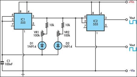
This timer utilizes two 555 integrated circuits (ICs) to adjust the desired output. The variable resistors VR1 and VR2 serve as potentiometers to modify the cycle speed. The circuit can be powered with a 9 to 12-volt power supply,...
The objective of this circuit is to power a lamp or other device for a predetermined duration (30 minutes in this instance) and subsequently turn it off. This functionality is particularly beneficial for reading in bed at night, as...
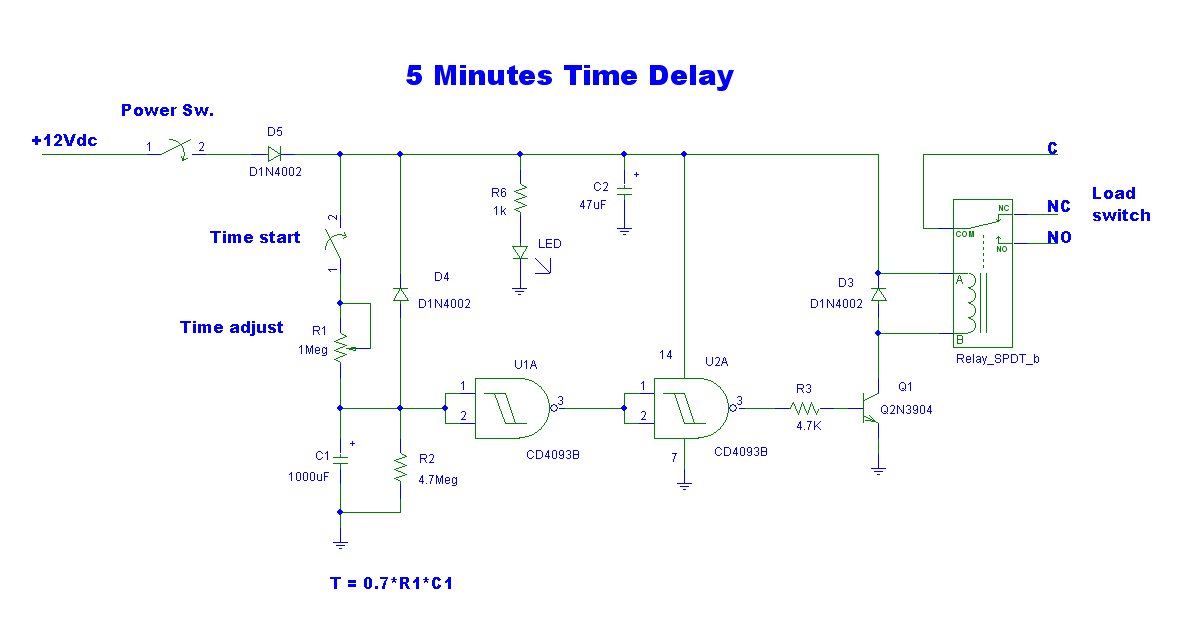
This is a simple delay timer circuit model designed to control the timing of electrical appliances. It provides a delay of approximately 5 minutes before turning off the connected devices. The delay timer circuit functions by utilizing a timing mechanism...
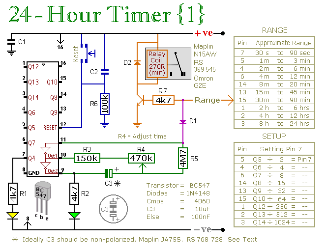
A pair of multi-range timers capable of timing periods up to 24 hours and beyond. Both versions are fundamentally similar, with the primary distinction being that Version 1 energizes the relay when the time expires, while Version 2 de-energizes...
This ultra wide range timer utilizes a 555 timer as its core component, along with two 4017 decade counters and a 4020 binary counter that function as frequency dividers, which can be selectively switched in and out. Additionally, the...

A pair of multi-range timers that provide timing periods extending up to 24 hours and beyond. Both timers are fundamentally identical, with the primary distinction being their relay behavior upon the completion of the timing cycle. Version 1 activates...