
two cmos based 24 hour timers

The multi-range timers are designed to provide versatile timing solutions for various applications, such as automation, control systems, and industrial processes. Each timer can be configured for different timing ranges, allowing users to set precise timing intervals according to their needs.
Version 1 operates by energizing a relay output upon completion of the set time period. This configuration is ideal for applications where an action needs to be triggered at the end of a timing cycle, such as activating a motor or turning on a light. The relay remains energized for the duration of the timing period, ensuring that the connected load receives power without interruption. This version is particularly suited for scenarios where the timing circuit must remain active, as it minimizes power consumption during operation.
In contrast, Version 2 is designed to de-energize the relay once the timer reaches the designated time limit. This approach is beneficial for applications where it is critical to cut off power to a device or circuit after a specified duration, such as in safety systems or energy-saving applications. By consuming less power after the timer has completed its cycle, this version enhances energy efficiency, making it an optimal choice for applications where prolonged power consumption is undesirable.
Both versions utilize a user-friendly interface for setting the desired timing intervals, often incorporating a digital display for easy readability. The timers may also feature adjustable settings for different timing modes, such as continuous, one-shot, or repeat cycles, providing flexibility for various operational requirements.
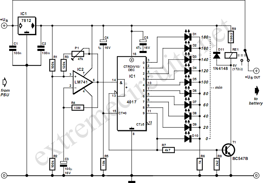
Overall, the choice between Version 1 and Version 2 should be made based on the specific needs of the application, considering factors such as power consumption, load requirements, and the desired relay action upon timer completion.A pair of multi-range timers offering periods of up to 24 hours and beyond. Both are essentially the same. The main difference is, that when the time runs out, Version 1 energizes the relay and Version 2 de-energizes it. The first uses less power while the timer is running; and the second uses less power after the timer stops.
Pick the one that best suits your application.. 🔗 External reference
Related Circuits
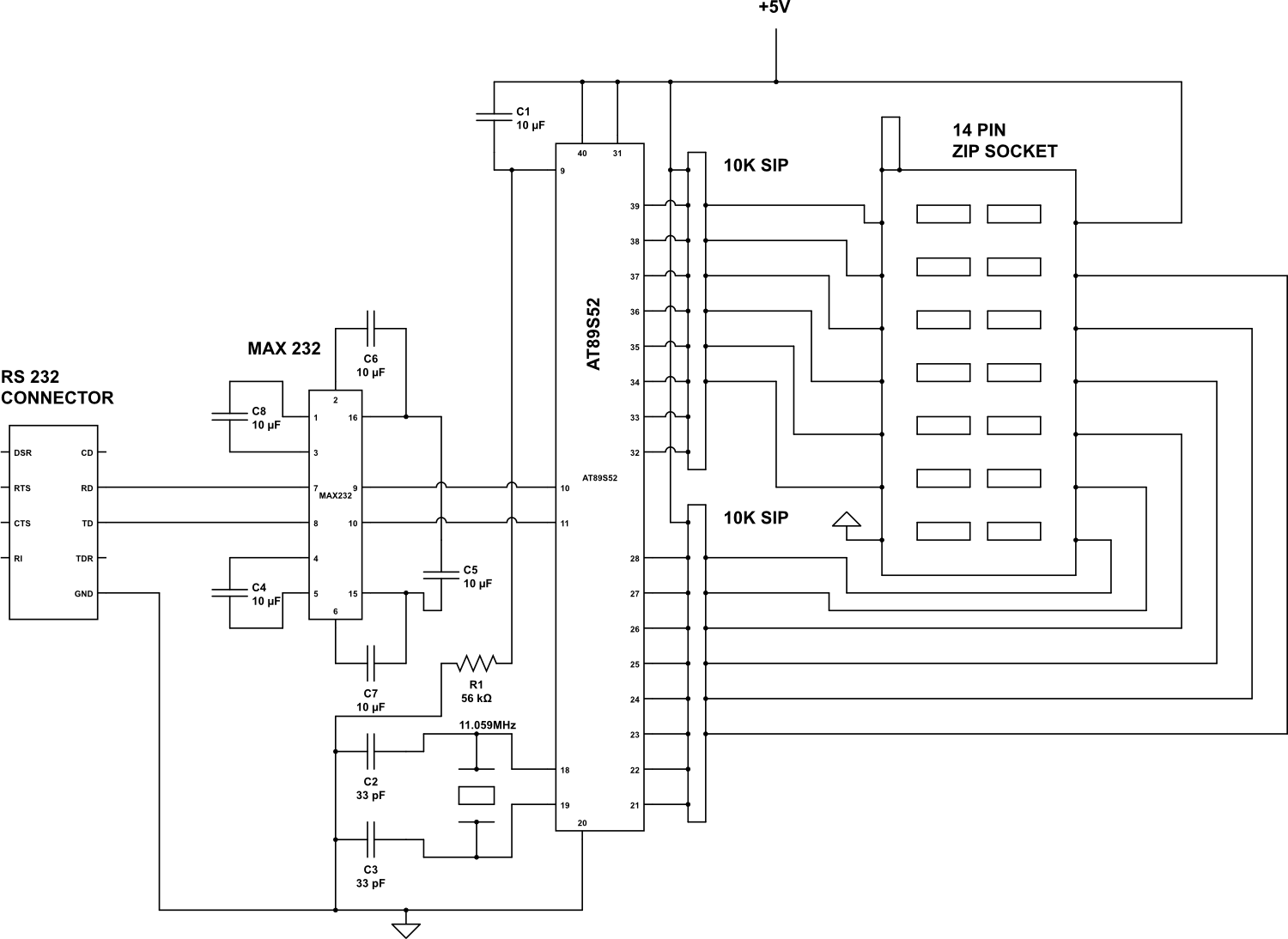
Check the following ICs: 7400, 7402, 7404, 7408, 7432, 7486. A Visual Basic program is utilized to display the results on the PC. The microcontroller AT89S52 receives the IC number from the PC, verifies the logic gates with the...
Manufacturers of cordless drills typically recommend a battery charging time of three hours. Once this charging time is complete, the battery must be disconnected from the charger to prevent the risk of overcharging. This circuit, positioned between the charger...
The capacitor charges until the PNP transistor (here shown as a 2N3906, but you could also use a BC327) receives base current through the Zener and turns on. Then the NPN transistor (here shown as a 2N3904, but you...
Switching to alternative power sources can help reduce electricity bills. The photovoltaic module or solar panel described here is capable of generating renewable energy. The photovoltaic module, commonly known as a solar panel, is a device that converts sunlight into...
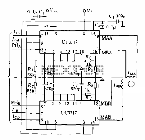
A typical application of a two-phase stepper motor is illustrated in Figure 5-15. It consists of two UC3717A components that can create a microcomputer control system for a two-phase permanent magnet or hybrid stepping motor. The control signals for...
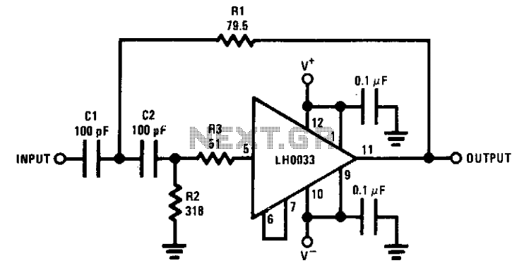
The circuit features a cutoff frequency of 10 MHz. Resistor R3 is utilized to prevent the input capacitance of the amplifier from affecting the filter response at the desired frequency. An equivalent low-pass filter can also be derived through...