
Controlling DC Motors Robotics Tutorial

The interface between DC motors and microcontrollers is critical in many applications, including robotics and automation systems. The Robocore board serves as a versatile platform that simplifies the control of multiple motors while providing essential debugging features through its LED indicators. The use of transistors as electronic switches allows for efficient control of motor operations without the need for high-current signals from the microcontroller. Each transistor pair is strategically selected based on the required current and voltage ratings of the motors, ensuring reliable performance.
The flyback diodes are an essential component of the circuit, as they protect the transistors from voltage spikes caused by the inductive loads of the motors. When a motor is de-energized or its direction is reversed, the collapsing magnetic field generates a back EMF that can exceed the rated voltage of the transistors. Properly rated flyback diodes provide a safe path for this reverse current, effectively shunting it away from the transistors and preventing damage.
When designing the circuit, careful consideration must be given to the power supply requirements. The voltage rating should match the specifications of the motors to ensure optimal performance. Additionally, when employing separate power supplies for the microcontroller and motors, it is crucial to connect the grounds to maintain a common reference point, preventing erratic behavior or circuit malfunction.
In summary, the integration of DC motors with microcontrollers like the Basic X through the Robocore board presents a robust solution for various applications. The careful selection of components, including transistors and flyback diodes, ensures reliable operation and longevity of the circuit, while proper power supply management is vital for successful implementation.The principles of DC motors are covered in the beginner and intermediate sections of this tutorial. This section will cover the electronics needed to interface them to a Basic X microcontoller or other digital chip. The easiest way of controlling motors is using the Robocore. This board contains the driver electronics to control up to 4 DC motors or 2 stepper motors, and features direction LED`s for easy debugging of circuits. Transistors are electronic switches, they allow you to turn on large voltages (the motor power supply) using a very small current (like the output pin of the Basic X). Each pair of transistors is connected to a pin on the micro controller and control the polarity of the current supplied to the motor.
The actual components required would depend on the size of the motors that you want to use. The diodes in the circuit are very important and are called fly back diodes. They are there to prevent voltage spikes from the motors from destroying the transistors. When a motor rotates and changes direction the coils of wire inside it act as a generator and produce a current. This current is called the back electro motive force, or back E. M. F. for short. This current travels back through the circuit, in the form of powerful voltage spikes, to the transistor.
Now, because transistors only allow current to flow in one direction the current hits a bottle neck as the transistor tries to stop the reverse current. If this current is particularly large, say when your reversing the direction of the motor, it will simply blow the transistor, giving your new circuit a pretty short life.
The circuit can be powered using whatever voltage is suitable for your motors. If you are using two power supplies, one to power your Basic X and another to power your motors, you must connect the ground of each supply together or your circuit may not work properly. 🔗 External reference
Related Circuits
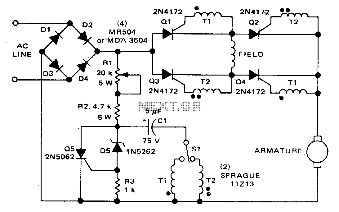
The circuit can control the speed and direction of rotation of a series-wound DC motor. Silicon controlled rectifiers Q1-Q4 are arranged in a bridge configuration and are triggered in diagonal pairs. The selection of which pair to activate is...
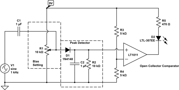
Control an LED with an audio signal; however, the output signal is only 150 mV peak-to-peak (with a 150 mV positive offset). It is understood that a higher voltage than 0.6 V is required to activate the transistor, leading...
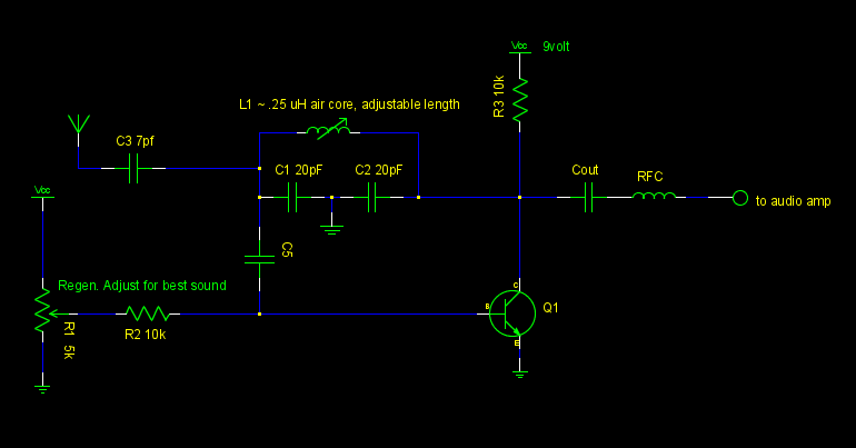
A common emitter Colpitts oscillator was constructed using variable capacitors for C1 and C2, and a few turns of wire wrapped around a pencil for the inductor L. Resistors R1 and R2 were replaced with a trimmer potentiometer to...
Current sensing involves detecting the amount of current being used by a specific circuit or device. It is particularly useful for assessing the power consumption of various components within a robotic system. Although not commonly required in robotics, current...
The large servos shown alongside a Nokia 3310 mobile phone provide a reference for scale. The servo arms measure 12 cm in length, making them suitable for lifting a bank of solar panels. The local Model Aerodrome in Seaside...
The most essential schematic to understand for any robot, whether for beginners or advanced users, is the circuit designed to control the robot's power source. It is inadequate to connect a battery directly to all components and expect proper...