
Phase protective circuit of harmonic currents 2 b

The described circuits are designed to manage the operation of a thyristor contactor, referred to as KM, which is essential in applications where reliable phase protection is critical. The primary function of these circuits is to mitigate the risk of malfunction associated with break phase protection relays, which can occasionally fail to operate correctly or may become unresponsive.
To achieve this, the circuits incorporate various components that work together to monitor the electrical conditions and ensure that the thyristor contactor operates as intended. This includes the use of sensors to detect phase loss or irregularities in the electrical supply, which can trigger the control mechanism to either engage or disengage the contactor as needed.
Additionally, the circuits are designed to enhance the overall sensitivity and reliability of the protection device. This may involve the implementation of feedback loops, which provide real-time data about the operational status of the contactor and the connected load. Such feedback is crucial for making instantaneous adjustments to the control signals, thereby improving response times and reducing the likelihood of false trips.
Furthermore, the design may include redundancy features to ensure that even if one part of the system fails, the overall functionality is not compromised. This could involve multiple sensing elements or alternative pathways for control signals, ensuring that the thyristor contactor can still be activated or deactivated under fault conditions.
Overall, the integration of these circuits into a system enhances the robustness of the phase protection mechanism, ensuring that the thyristor contactor operates reliably under varying electrical conditions, thus protecting the connected equipment from potential damage due to phase loss or other electrical anomalies. Both circuits are used to control the thyristor contactor KM action to overcome the break phase protection relay prone to malfunction or refuse to move, and enhanced the sensit ivity and reliability of the protection device.
Related Circuits

This is a universal remote control that was constructed using 1KB of memory. It operates with televisions utilizing the RC5, RC80, and NEC protocols, which cover the majority of TV models. The remote has an effective range of approximately...
The optical safety switch circuit includes a power supply circuit, a light control circuit, and a control implementation circuit (switch circuit). The power circuit is made up of a power transformer (T), a bridge rectifier (UR), and a filter...
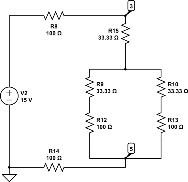
The Delta configuration of resistors R2, R3, and R4 is converted to a Wye (Y) configuration. This conversion is necessary because a voltage divider is typically employed in series circuits. The aim is to determine the total resistance in...
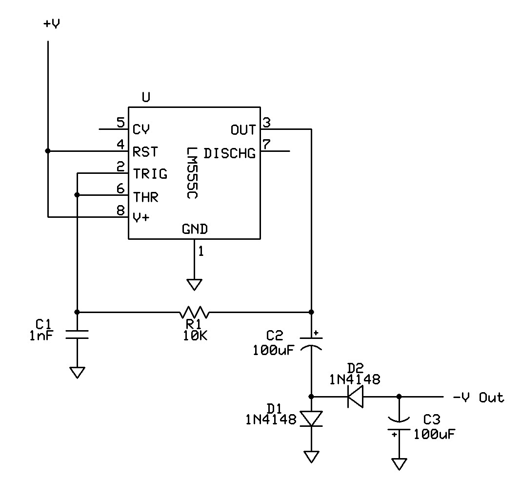
Can a 555 negative supply circuit, like the one below I pulled from another schematic, supply enough negative voltage to an LM324 and an AD736JN? The 555 timer integrated circuit can be configured to generate a negative voltage supply,...
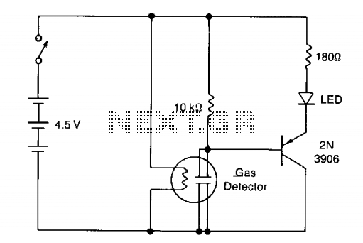
The circuit illustrates a basic yes/no gas detector. It utilizes three 1.5-V D cells as the power source, with SI functioning as an on/off switch. The heater is powered directly from the battery, while the electrodes are connected in...
A single-chip metal detector with a detection range of a few inches. This device is useful for identifying nails or screws in walls and floors, as well as locating buried mains cables. The core of the metal detector circuit...