5 Zone Anti TheftCircuit Based On The CMOS 4050B IC
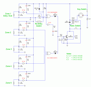
The following circuit illustrates a 5 Zone Anti-Theft Circuit Diagram. This circuit is based on the CMOS 4050B IC. Features: the system may comprise in...
The 5 Zone Anti-Theft Circuit utilizes the CMOS 4050B integrated circuit, which is a hex buffer and inverter. This circuit design is particularly effective for security applications, allowing for the monitoring of multiple zones simultaneously. Each zone can be equipped with various sensors, such as motion detectors or door/window contacts, to provide comprehensive coverage.
The configuration typically employs a series of input sensors connected to the CMOS 4050B IC. The outputs from the IC can be interfaced with alarm systems or visual indicators, such as LEDs, to alert users when an intrusion is detected in any of the zones. The CMOS technology ensures low power consumption, making the circuit suitable for battery-operated devices.
In this circuit, each zone is monitored independently, allowing for localized detection and response. The design may include additional components such as resistors, capacitors, and diodes to filter signals and manage power supply requirements effectively. The output from the CMOS IC can be connected to a microcontroller for further processing, enabling features like remote notifications or integration with smart home systems.
Overall, this 5 Zone Anti-Theft Circuit offers a robust solution for enhancing security in residential or commercial settings, leveraging the reliability and efficiency of the CMOS 4050B IC.The following circuit shows about 5 Zone Anti Theft Circuit Diagram. This circuit Based On The CMOS 4050B IC. Features: system may comprise in .. 🔗 External reference
