
50-300mW FM Transmitter With TX300

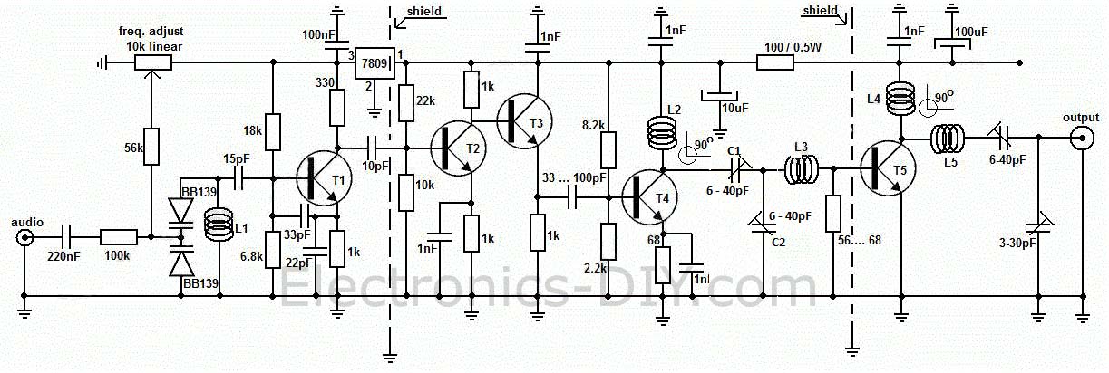
The FM transmitter circuit is designed to operate within a power range of 50 to 300 milliwatts, making it suitable for various applications such as amateur radio broadcasting and low-power audio transmission. The core of the circuit utilizes the TX300 integrated circuit, which is specifically designed for FM transmission tasks.
The schematic typically includes essential components such as a power supply, audio input stage, modulation circuit, and an output stage for RF amplification. The power supply section is responsible for providing a stable voltage to the circuit, often derived from a battery or a regulated power source.
The audio input stage may consist of capacitive coupling to filter out DC components, allowing only the audio signal to pass through. This audio signal is then fed into the modulation circuit, where it is mixed with a carrier frequency generated by an oscillator circuit within the TX300. The modulation process alters the amplitude of the carrier wave based on the audio input, producing an FM signal.
Following modulation, the RF output stage amplifies the modulated signal to the desired power level, ensuring effective transmission over a specific range. Antenna matching components may also be included to optimize the output for the antenna, enhancing transmission efficiency.
Overall, this FM transmitter circuit is designed for simplicity and effectiveness, making it accessible for hobbyists and engineers looking to explore FM transmission technology.50-300mW FM Transmitter With TX300 Electronic Circuit Schematic Wiring Diagram. 🔗 External reference
Related Circuits

This small transmitter employs a Hartley-type oscillator. Typically, the capacitor in the tank circuit connects to the base of the transistor; however, at VHF frequencies, the base-emitter capacitance of the transistor behaves like a short circuit, maintaining effective operation....
Using a Motorola MC2833 one-chip FM transmitter, a few support components, and an MPF6660 FET RF amplifier, this transmitter delivers approximately 3 W into a 50-ohm load. It is capable of operation over a frequency range of about 29...
This circuit is a long-range, highly stable, harmonic-free FM transmitter designed for FM frequencies between 88 and 108 MHz. With an appropriate antenna, it can cover a range of up to 5 km. The circuit features a stable oscillator...
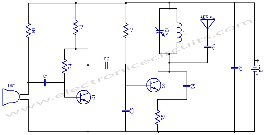
This project provides the schematic and the parts list needed to construct a 3V FM transmitter. This FM transmitter is one of the simplest and most basic transmitters to build, yet it offers a useful transmitting range. It is...
This transmitter emits an FM signal within the 88 to 108 MHz frequency range, featuring a tone of 19 kHz. This tone can activate the FM MPX pilot carrier indicator, allowing interfacing with external devices. L4 is designed for...
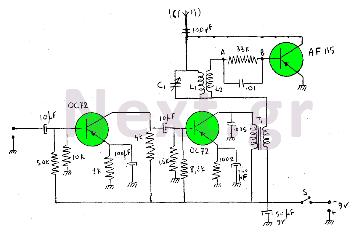
This device is a transmitter operating on medium-wave and short-wave frequencies, utilizing three transistors. The AF115 transistor serves as the oscillator within the circuit. The low-frequency amplifier, consisting of two OC72 transistors, functions as the modulator that generates the...