
27.125Mhz Nbfm Transmitter Circuit

The described FM transmitter circuit utilizes the Motorola MC2833 integrated circuit, which serves as the core component for FM signal generation. This chip is designed to provide efficient modulation of audio signals onto a carrier wave, making it suitable for short-range broadcasting applications. The MC2833 operates within the specified frequency range of 29 to 32 MHz, allowing for flexibility in tuning and transmission.
Support components are essential for the proper functioning of the MC2833. These components typically include resistors, capacitors, and inductors that help in setting the frequency of oscillation, filtering unwanted harmonics, and stabilizing the circuit. Proper selection and arrangement of these components are critical to ensuring that the transmitter operates within its intended specifications and provides a clean output signal.
The RF amplification stage is achieved using the MPF6660 FET, which is a field-effect transistor known for its high gain and low noise characteristics. This amplifier boosts the output power of the FM signal to approximately 3 watts, which is sufficient for short-range transmission. The output is designed to match a 50-ohm load, which is a standard impedance for RF applications, ensuring maximum power transfer and minimizing signal reflections.
The circuit can be further enhanced with additional features such as a low-pass filter to suppress harmonic frequencies, a power supply regulation circuit to ensure stable operation, and an audio input stage to interface with various audio sources. The overall design of the transmitter must consider factors such as heat dissipation, component tolerances, and layout to achieve optimal performance and reliability in real-world applications. Using a Motorola MC2833 one-chip FM transmitter, a few support components, and an MPF6660 FET RF amp, this transmitter delivers about 3 W into a 50- load. It is capable of operation over about 29 to 32 MHz with the components shown.
Related Circuits
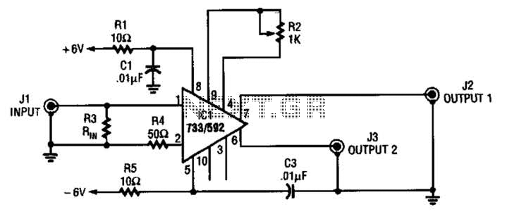
This circuit selects one of two channels using a logic signal. The unused channel is shorted out to minimize crosstalk. The bandwidth at -3 dB is approximately 8 MHz. It is recommended to buffer this circuit due to some...

Assistance is required to modify a light dimmer circuit connected to a PIC12C508 microcontroller. This circuit is designed for the... The light dimmer circuit utilizing the PIC12C508 microcontroller serves to control the brightness of a light source through pulse width...
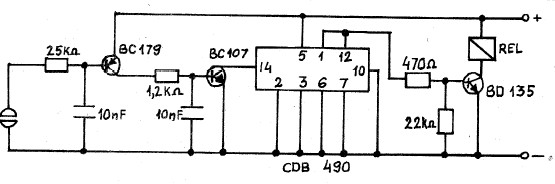
This 555 timer circuit toggles a relay when a button is pressed. Pins 2 and 6, which are the threshold and trigger inputs, are maintained at half the supply voltage by two 10K resistors. When the output is high,...
A collection of touch switch circuits is presented. A touch switch is an electronic device that allows control of a circuit simply by touching a sensor. The circuit diagram illustrates a simple design that utilizes only eight components. The...

An amplifier circuit is designed to handle an assumed input consisting of two equal and opposite polarity signals, known as a differential mode signal. The two tube collector currents, Ic and IC7, are balanced in such a way that...
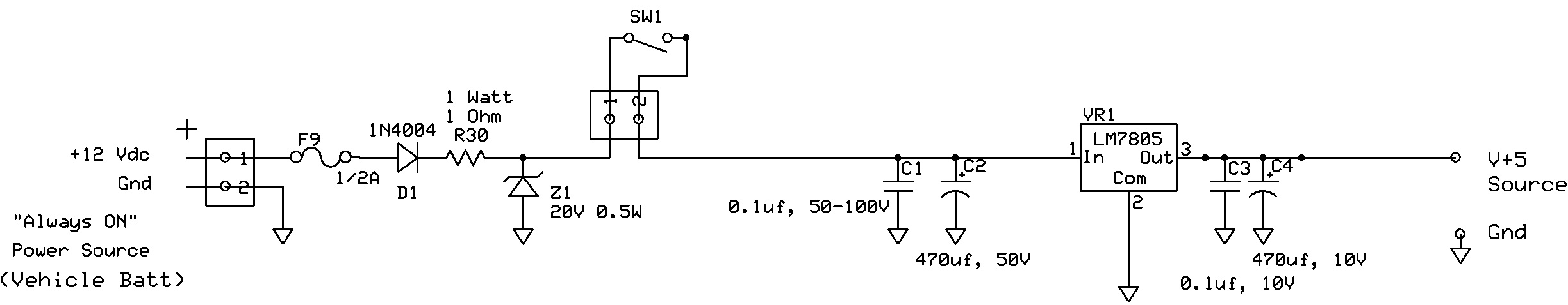
The circuit regulates approximately 12V from the car battery down to 5V for use by an Atmel AVR microcontroller. The presence of two capacitors on each side of the linear regulator LM7805 raises questions regarding their purpose. It is...