
Remote-Control Transmitter Circuit

The described FM transmitter circuit operates within the standard FM broadcast band, specifically designed to transmit signals that can be received by standard FM radios. The 19 kHz tone is significant as it serves as a pilot tone for multiplexing, which is essential for stereo FM broadcasting. This pilot tone enables the receiver to recognize the presence of a stereo signal, thus activating the stereo decoder circuitry in compatible receivers.
The antenna (L4) is optimized for the 15 cm length, which is crucial for efficient transmission at the specified frequency range. The choice of wire gauge, #26, provides a balance between flexibility and resistance, ensuring that the inductors maintain their intended inductance values without excessive losses.
Inductor L1 is constructed with 9 turns of enameled wire, which helps form a resonant circuit in conjunction with the carbon resistor. The 54-ohm resistor is selected to match the impedance of the circuit, optimizing power transfer and minimizing reflections. L2, being only 2 turns wound over L1, serves as a coupling inductor that enhances the signal transfer between stages of the circuit.
Inductor L3, with 7 turns of #26 enameled wire on a 10-kΩ, ¼-W resistor, plays a role in filtering or further modifying the signal characteristics. The choice of a carbon resistor for L1 and L3 indicates a preference for stability and reliability in the circuit's performance.
Overall, this circuit design highlights the importance of careful component selection and configuration in achieving a functional FM transmitter capable of interfacing with external devices and providing high-quality signal transmission within the FM band. This transmitter sends an FM signal in the 88-to 108-MHz range, with a tone of 19 kHz. This can be used to activate the FM MPX pilot carrier indicator, which can be interfaced to external devices. L4 is for use with a 15 CM wire antenna. LI is 9 turns of #26 enamelled wire on a 54-W 10-kQ resistor (carbon type), L2 is 2 turns wound over LI.
L3 is 7 turns of #26 enamelled wire on a 10-ka /4-W resistor.
Related Circuits
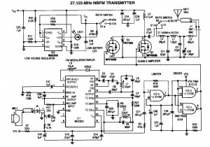
A 27MHz NBFM transmitter circuit schematic featuring the MC2833 and two MPF6660 FET transistors. Utilizing the Motorola MC2833 one-chip FM transmitter along with several supporting components and an MPF6660 RF amplifier, this transmitter can deliver up to 3W into...
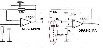
Can someone explain why there is an LC filter in the op-amp circuit? Additionally, are there any modifications that can be made to enhance the sound quality? The presence of an LC filter in an operational amplifier (op-amp) circuit serves...
Any ideas? Is this circuit going to be standalone? Is there any other circuitry around it, perhaps a microcontroller? What circuitry does the timing device contain, or does it even contain electronics? Abdullah Kahraman Mar 22, '13 at 18:10....
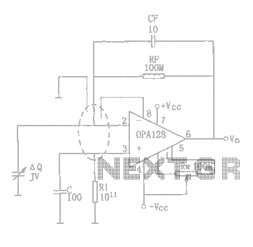
A charge amplifier is designed to amplify the signal charge from a piezoelectric device. It features a high internal impedance to accommodate the weak signal charge, which can be at the picoampere (pA) level. This necessitates a charge amplifier...
A circuit diagram for an animal repeller is provided. The circuit has been developed but is not functioning as intended. Assistance is requested for troubleshooting. The animal repeller circuit typically employs ultrasonic sound waves to deter animals from specific areas....
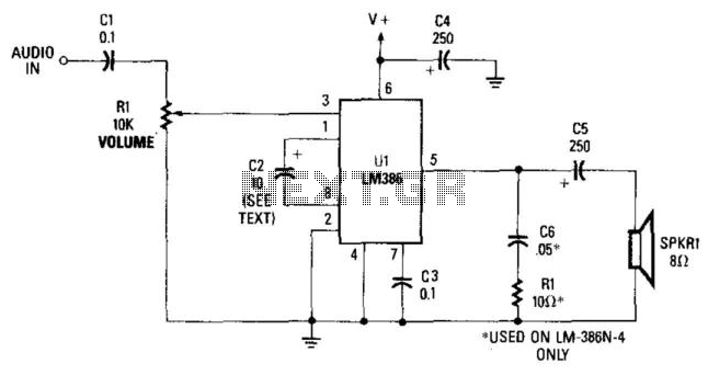
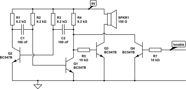
This simple receiver AF amplifier can supply several hundred milliwatts to an 8-ohm speaker. The gain is approximately 200X. If high gain is not required, C2 can be removed, resulting in a gain of 20. R1 and C6 are...