
50 impedance RF2320 linear amplification circuit diagram

The RF2320 linear amplifier circuit is designed to operate with a 50-ohm impedance, which is a standard value in RF applications, ensuring optimal power transfer and minimal signal reflection. The input and output stages of the amplifier utilize transmission lines, which are critical for maintaining signal integrity and minimizing losses. These transmission lines can be implemented using microstrip or stripline technologies, depending on the PCB design and the desired frequency characteristics.
The matching network is an essential component in this circuit, as it ensures that the amplifier is properly matched to the source and load impedances. This matching can be achieved through the use of inductive or capacitive components, which can be configured in various ways, such as L-networks, T-networks, or π-networks, depending on the specific requirements of the application. The choice of components and their values will depend on the frequency of operation and the specific characteristics of the RF2320 amplifier.
Properly designing the matching network involves calculating the necessary component values to achieve the desired impedance transformation. This can be accomplished using techniques such as Smith chart analysis or computer-aided design (CAD) tools to simulate the circuit performance. The goal is to achieve a flat frequency response over the desired bandwidth while maintaining low insertion loss and high return loss.
In summary, the RF2320 linear amplifier circuit, with its 50-ohm impedance configuration, effectively utilizes transmission lines and matching networks to optimize performance for RF applications. The careful selection and arrangement of inductive and capacitive components are crucial for achieving the desired operational characteristics.50 impedance as shown in Figure grounds RF2320 linear amplifier circuit configured, input, output, using the transmission line and inductive or capacitive constitute matching n etwork.
Related Circuits
The circuit is based on four integrated circuits: TL072, TL074, MN3101, and MN3004, which produce four output channels for surround audio, specifically targeting center, rear, front right, and front left audio. It is a compact amplifier capable of delivering...
The vacuum tube remains relevant and functional in certain applications, such as in this continuous wave (CW) transmitter. The circuit is constructed in a traditional breadboard style on a wooden base. Old table radios serve as a valuable source...
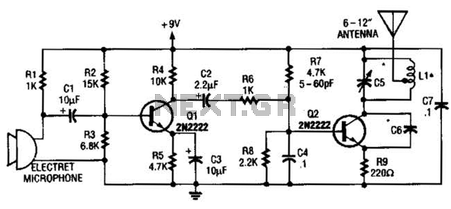
The frequency range for the FM transmission band is 90 MHz (megahertz, or 90 million cycles per second). Due to the variable tuned circuit in the FM transmitter, it can be tuned to a specific frequency within the local...
This project involves a 12V LED lamp circuit that is notably simple. The circuit comprises five resistors and fifteen super bright white 5mm LEDs, which are readily available at low prices. It is compatible with any type of 12-volt...

When the power supply reaches the circuit and the input signal is applied, the sound signal is processed through capacitor C1 and resistor R1 for signal coupling and noise reduction. The modified signal then reaches pin 3 (non-inverting) of...
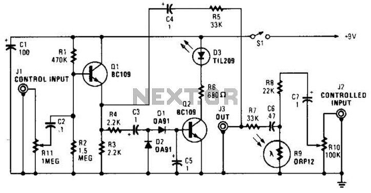
In this circuit, audio input to the control channel is amplified and rectified by diodes D1 and D2. This direct current level activates LED D3 through transistor Q2. The illumination from LED D3 causes R9, a light-dependent resistor, to...