
wireless microphone circuit

The FM transmitter circuit operates within the specified frequency range of 90 MHz, which is crucial for compatibility with standard FM radio receivers. The inclusion of a variable tuned circuit allows for precise frequency adjustment, enabling the transmitter to be aligned to a specific frequency that minimizes interference and maximizes clarity.
The small microphone serves as the transducer, converting acoustic energy from sound waves into electrical energy. This conversion occurs through a diaphragm that vibrates in response to sound, generating a corresponding change in current. Resistor R1 plays a critical role in this process by providing a load for the microphone and helping to shape the signal for amplification.
The amplified signal is then fed into a modulator circuit, which applies frequency modulation to the carrier wave generated by an oscillator. This modulation process encodes the audio information onto the carrier wave, allowing it to be transmitted over the airwaves.
The operational range of the FM microphone, approximately 100 feet, is influenced by several factors. The design and tuning of the antenna significantly affect the transmission range, as a well-tuned antenna can efficiently radiate the modulated signal. Additionally, the sensitivity and selectivity of the receiving FM radio also play a vital role in determining the effective range and quality of the received signal.
In summary, this FM transmitter circuit is designed for effective audio transmission over short distances, utilizing a combination of microphone conversion, amplification, and frequency modulation to deliver clear sound to standard FM receivers. Proper tuning and antenna design are essential for optimal performance.The ambit of frequencies for the FM advertisement bandage is 90MHz (MHz = Megahertz or 90 actor cycles per second). Because the FM microphone has a capricious acquainted circuit, it can be acquainted to a quiet atom on your bounded FM advertisement bandage for the best reception.
When the baby microphone aspect is addled by sound, it converts the audio to a change in accepted through resistor R1 (see schematic diagram). This electrical change is amplified and eventually abundance modulates the transmitter. The manual ambit of the FM microphone is about 100 feet, depending on the ability of the antenna (properly acquainted or not) and the affection of the FM radio receiver. 🔗 External reference
Related Circuits

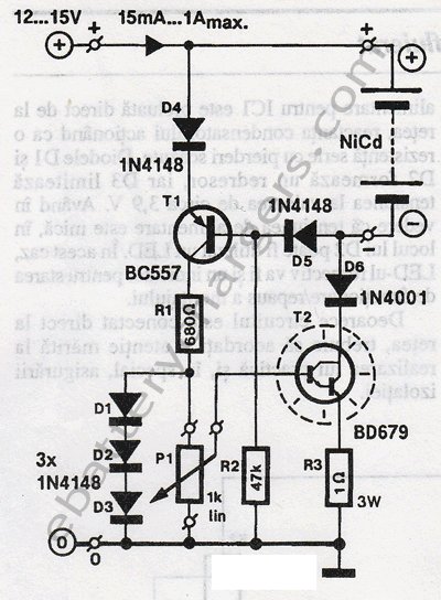
The best 12 Volt battery charger circuit is an automatic system that activates when the battery voltage falls below a specified threshold. This 12 Volt battery charger circuit is designed to efficiently charge lead-acid batteries while ensuring safety and longevity....
This circuit is designed to signal the exceeding of a fixed threshold in room noise through a flashing LED. Three fixed levels are selectable: 50, 70, and 85 dB. Two operational amplifiers provide the necessary gain for sounds captured...

This design circuit is a tone control circuit that utilizes the popular Baxandall configuration, a straightforward circuit layout that allows for continuous boost and cut control. The circuit is inexpensive to construct and is frequently implemented in commercial products....
Two-Tone Siren Circuit Schematic Using One IC. This circuit is designed for children's entertainment and can be installed on bicycles, battery-powered cars, motorcycles, as well as models and various games and toys. It includes a switch (SW1) for operation. The...
This is a light sensor circuit designed to detect light and activate a relay. The circuit is straightforward and requires only a few components. The operation of the circuit is simple: when the photoresistor detects light, it will turn...
This 24V to 36V linear battery charger is long overdue. While this is an old circuit technique, it is optimized for charging higher voltage lead-acid batteries. The 24V to 36V linear battery charger is designed to provide a stable charging...