
50 MHz Receiver

The circuit design integrates the MC3372 FM receiver chip, which operates effectively within the specified 50MHz range. The use of an LC tank circuit or a crystal oscillator allows for precise tuning, enabling the reception of various frequencies. The antenna preamplifier, utilizing a dual gate MOSFET, enhances the signal strength before it reaches the main receiver circuit, thus improving overall sensitivity and reception quality.
The inclusion of a 455kHz ceramic filter ensures that only the desired frequency band is processed, minimizing interference from other signals. The choice of a sharper filter, typically found in cordless phones, can further refine selectivity, allowing for clearer audio reception. The hand-wound coils, L1 and L2, are critical components for impedance matching and tuning. The specified coil dimensions and winding turns are tailored to achieve approximately 650 nH inductance, which is optimal for the operating frequency.
The design also emphasizes the importance of antenna placement and connection points. By experimenting with different tap points, users can fine-tune the receiver's performance to suit their specific environment and signal conditions. The use of an RSSI output for real-time monitoring facilitates adjustments to the preamplifier, ensuring that the receiver operates at peak efficiency.
The audio demodulation section, featuring a quad coil tuned to 455kHz, is designed to decode the received signal into an audible format. The operational amplifier enhances the audio output, while the squelch unit helps eliminate unwanted noise during silent periods, providing a cleaner listening experience.
Overall, this receiver design is a versatile and sensitive solution for capturing a wide range of signals, suitable for both audio and data transmission applications. The compact design housed in a metal case ensures durability and reduces electromagnetic interference, making it an excellent choice for various practical applications.The purpose of this project is to build a simple receiver for 50MHz. The Receiver is built around the circuit MC3372, wich is a narrow band FM receiver. The receiving frequency can be set with a LC tank or with a crystal. To increase the sensitivity of this circuit I have added a antenna preamplifier. I have found a circuit MC3371/MC3372 wich is very simple circuit to handle. I wanted to build a receiver wich can handle all kinds of signals. I both want to receive audio and data. To increase the sensitivity, I have added a dual gate input FET amplifier. The complete receivier will be built into a metal-case and used with a external audio amplifier or microcontroller. As you can see the circuit contains everything one need for a receiver. The 455kHz ceramic filter is a narrow band filter. You can find 455kHz keramic filter in AM section in some old radio. However the best filter is a sharper type found most often in old cordless phones, maybe there is some place to order them. The preamplifier consist of a dual gate mosfet. I have fall inlove with the type BF990 and BF 991. They are surface mounted and have good performances. You can use many different types, just check that they have low noise value and high gaing. There are two hand made coils in this construction, L1 and L2. I used a drill with 7.2 mm diameter and I made them 10 turns. It will give you about 650 nH. Coil L1 is taped at 5 turns. This is to impedance match the preamplifier with the MC3372 circuit. How do I know the tap should be at 5 turns, well I have been testing my receiver with different tap points and I have found that a tap at 5 turns will give you the best performance.
You can play yourself with different taps and test your receiver. The antenna should also be connected to a tap point close to the cold side of the coil to give the best performance, see my Front end design of antenna page to understand why. Well, I have also made some field test and I have found that the best performance will be if the antenna (80cm wire) is connected to the top of the coil.
The selectivity will not be so good, but the overal performance will till be best this way. If you want you can play with this tap also. I made one receiver with the antenna connected to tap point at 5 turn and the receiver worked well. To find the best performance you should attach a voltmeter to the RSSI output and tune the preamplifier for best readings. Easiest is if you use an analogue instrument. The audio demodulator is a LC unit (quad coil) tuned to 455kHz. This type of quad-coils is often found in AM radios. It is a CAN with yellow slug. The MC3372 can be used with a ceramic resonator instead of quad coil. Inside the circuit is a operational amplifier wich can be used to amplify the audio signal and there is a squelch unit.
The circuit need just a few componets to work, and the sensitivity is under 1 uV. I have still added a preamplifier to improve the selectivity and the input stage. If you want you can exclude the preamplifier, but the reciving will not be as good. 🔗 External reference
Related Circuits
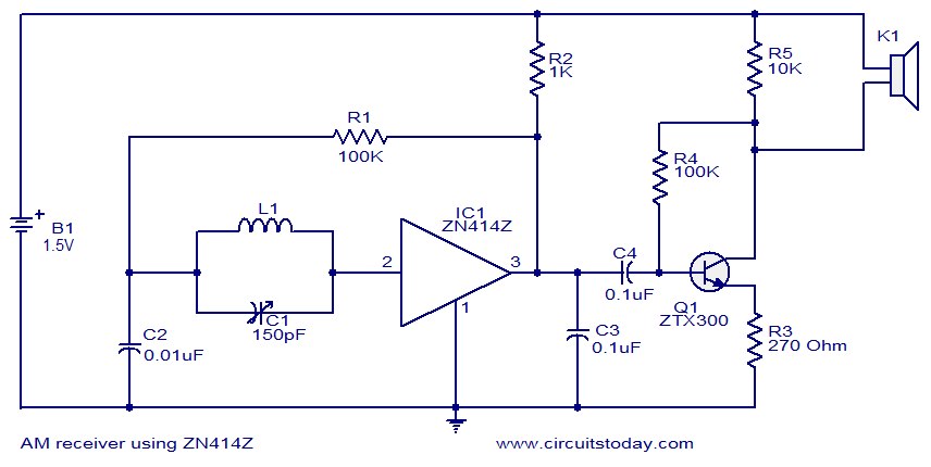
This circuit diagram represents a simple single-chip AM radio, designed around the ZN414Z integrated circuit (IC), which is a ten-transistor tuned radio frequency receiver. The IC features three leads and is housed in a TO92 package. It incorporates all...
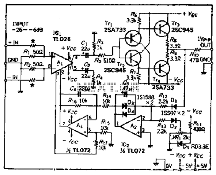
A car circuit is utilized for external voltage-controlled amplification in wideband amplifiers using the TL0216 IC. This design incorporates compression characteristics of 2dB. The input circuit consists of resistors that reduce the input level when it is between -26dB...
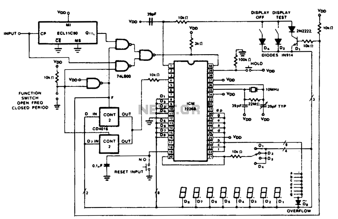
The figure illustrates the application of a CD4016 analog multiplexer to route digital outputs back to the FUNCTION input. The CD4016 functions as a digitally controlled analog transmission gate, eliminating the need for level shifting of the digital output....
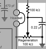
The antenna coupling capacitor is an essential component in a regenerative receiver that does not include an RF stage, such as the Twinplex. In this type of receiver, the antenna is a vital part of the regenerative detector, and...
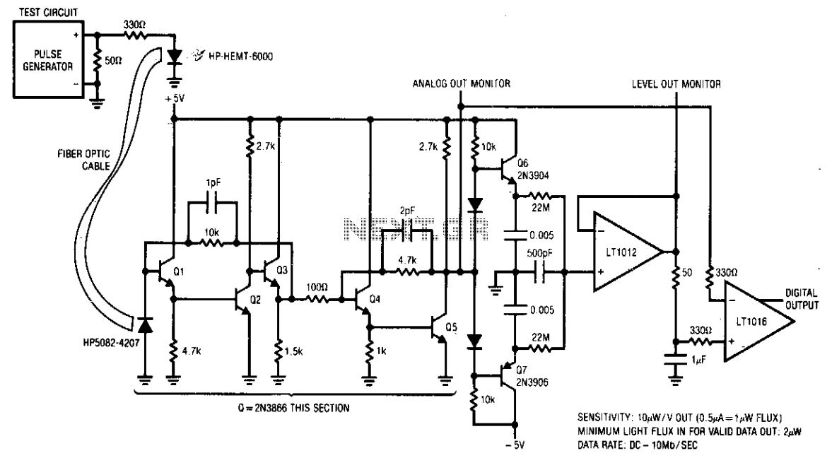
The receiver is designed to accurately condition a wide range of light inputs at data rates of up to 10 MHz. The optical signal is detected by a PIN photodiode and amplified by a broadband feedback stage comprising transistors...
A circuit designed to operate within a frequency range with an accuracy greater than 2% for generating Bode plots. It converts two sine waves into a square wave, taking into account the overlap relative to the total input wave...