
50 Watt Amplifier Circuit Using Transistor

This power amplifier circuit is designed for durability and ease of assembly, making it suitable for both hobbyists and professionals. The Class B configuration allows for efficient operation, minimizing distortion while providing substantial power output. The 2N3055 transistors are known for their high current handling capability and thermal stability, making them ideal for driving speakers in audio applications. The pre-amplifier stage ensures that the input signal is adequately boosted before reaching the driver stage, allowing for better overall performance.
The choice of capacitors in this circuit is critical; C1 is typically a larger value capacitor designed to pass lower frequencies, enhancing bass response, while C2, being smaller, allows higher frequencies to pass through, ensuring clarity in the audio output. The adjustable 500 Ohm potentiometer connected to the BC107 transistor allows for fine-tuning of the amplifier's output power, accommodating various speaker impedances and ensuring compatibility with different audio sources.
The power supply requirements highlight the importance of using a well-regulated and filtered supply to prevent noise interference, which can significantly affect audio quality. The option to use a 10K potentiometer for volume control provides flexibility in adjusting the sound level to suit the listening environment. Overall, this amplifier circuit is a practical solution for achieving high-quality audio amplification in various settings, from home audio systems to small public address systems. Proper assembly and component selection will ensure reliable operation and longevity of the amplifier.It is very rugged and reasonably power amplifier circuit that can be used for any audio applications. The amplifier produces 60W rms at 50V supply on a 8 Ohm load. The circuit is designed such that most of the components are not critical and can be easily replaced by nearest values.
This make it ideal to assemble from your electronics junk box. Th is is a good design for room audio. This circuit is based on transistor for the operation. This is the figure of the circuit. The capacitor C1 controls low frequencies and capacitor C2 controls high frequencies. The circuit is basically a class B amplifier. The transistors 2N 3055 serves the function of driving the speaker. The other transistor functions as pre amplifiers for the driver stage. This is the basic scheme of the circuit. The maximum power level of amplifier can be set by adjusting the 500 Ohm POT connected with the BC107 transistor. The circuit can be powered using a 50 V DC power supply with 5A current rating. Power supply up to 60 V can be given to the circuit. Any way the power supply must be well regulated and filters to avoid noise. Volume control can be attained by connecting a 10 K POT in series to the input of the amplifier, but in the figure is not shown.
Adjust the 500 ohm POT to obtain optimum performance. All capacitors must be rated higher than the supply voltage. 🔗 External reference
Related Circuits
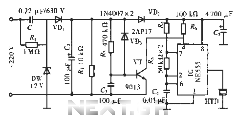
The circuit utilizes a 555 integrated circuit (IC). When an incoming call is received, 220 V AC is stepped down through resistor R1, followed by rectification using diode VD1. A voltage regulator (DW) is employed, and capacitor C2 is...
A 2 x 18W Hi-Fi Stereo Power Amplifier is designed using two TDA2030 integrated circuits (ICs). This amplifier features excellent input sensitivity, low distortion, robust operating stability, and comprehensive protection against overloads and output short-circuits. It is suitable for...

An RF power amplifier is an electronic amplifier used to convert a low-power radio-frequency signal into a larger signal of significant power, typically for driving the antenna of a transmitter. It is optimized for high efficiency, high output power...
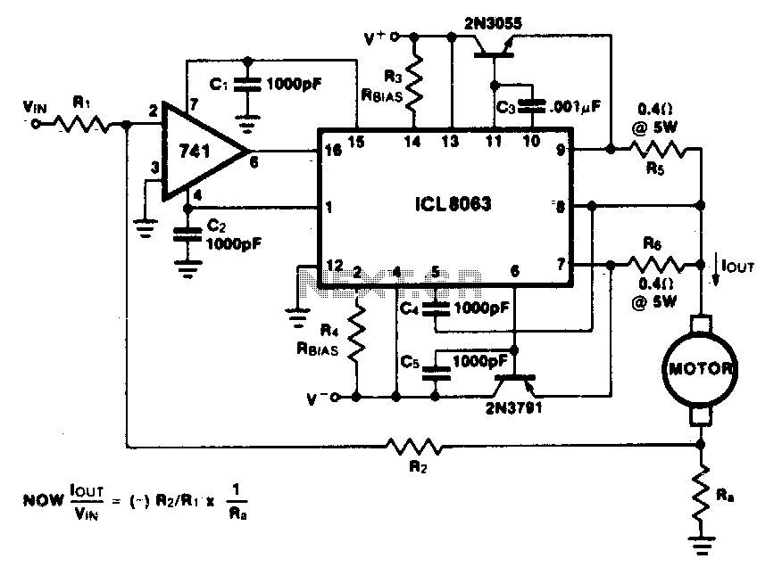
This minimum device circuit can be used to drive DC motors where there is some likelihood of stalling or lock-up. If the motor locks, the current drive remains constant, and the system does not destroy itself. This circuit is designed...
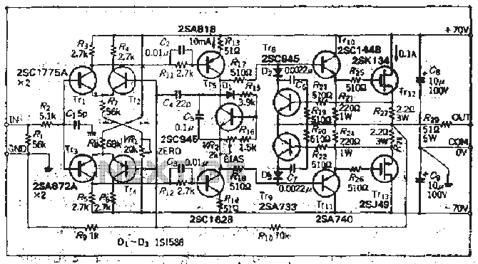
The south circuit consists of four parts, arranged in descending order: an NPN transistor dynamic garbage device (T1), a PNP transistor differential amplifier (T2, T3) forming a double differential circuit, two balanced output amplifiers with opposite phase, and a...
This intelligent electronic lock circuit is constructed using only transistors. To unlock this electronic lock, the user must press tactile switches S1 through S4 in sequence. For added security, these switches can be labeled with different numbers on the...