
500Watt Power Amplifier Circuit Schematic Diagram

The 500-watt mono power amplifier circuit is designed to deliver high output power while maintaining audio fidelity. The use of Sanken transistors, specifically the 2SC2922 and 2SA1216, is crucial as they are known for their high current handling and thermal stability, making them suitable for audio amplification applications. The configuration of four transistors in the output stage allows for efficient power delivery while minimizing distortion.
The power supply section of the circuit is critical, requiring a dual voltage transformer with a center tap. The transformer must provide a minimum of 10A to ensure that the amplifier can handle dynamic audio signals without clipping. The specified voltage range of 3-42 volts allows for flexibility in tuning the amplifier's output power and performance characteristics. The inclusion of a safety fuse is a vital feature, protecting the circuit from overcurrent conditions that could cause damage to the components.
For optimal performance, the circuit layout should be designed with attention to grounding and signal integrity. Proper decoupling capacitors should be placed near the power supply pins of the transistors to filter out any high-frequency noise. Additionally, heat sinks should be employed on the output transistors to dissipate heat generated during operation, ensuring reliable performance over extended periods.
Overall, this 500-watt mono power amplifier circuit schematic serves as a robust foundation for building a high-performance audio amplifier, suitable for various sound reinforcement applications.In this post I will publish the circuitschematic diagram of Power Amplifier with 500watt output mono, yesterday happened to date July 18, 2012 order I able to make Power Sound System 1000 watts stereo output, which is used Sanken Transistor Final original eight seeds, serial 2SC2922 and 2SA1216, while the circuit schematic that I made here just ne xt to it / mono with 4 Sanken transistors, let`s see diagram skematic 500Watt Power Amplifier Circuit: Power circuit requires consumption voltage polarity is 3 - 42Vol; + 42 Vol; CT 0 V and there is a safety fuse / voltage connecting Fuse Fuse is the only positive and negative voltage is connected, the source voltage / transformer CT minimum of 10A, AC Vol 220, 50 Hz. You are reading the Circuits of 500Watt Power Amplifier Circuit And this circuit permalink url it is 🔗 External reference
Related Circuits
A capacitance meter is an essential instrument for electronics hobbyists and professional electronic technicians. A capacitance meter is a specialized device used to measure the capacitance of capacitors in electronic circuits. It is a valuable tool for diagnosing and troubleshooting...
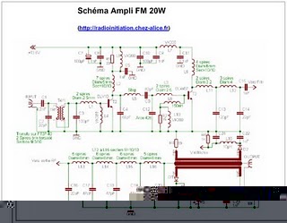
The following circuit illustrates an RF amplifier designed for FM frequencies ranging from 88 to 108 MHz with a broadband configuration. This circuit utilizes the BLV10 transistor. The RF amplifier circuit operates within the FM broadcast band, which is crucial...
Building a personal alarm system is both practical and engaging. The most rewarding aspect is demonstrating its functionality to friends by activating the alarm remotely, saying, "I completed this in a weekend." Customizing the alarm system offers maximum flexibility,...
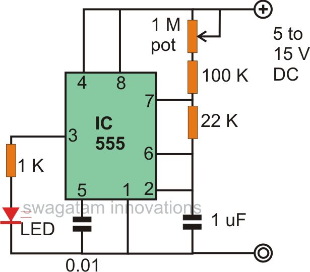
The astable multivibrator mode is the most basic operational mode of the IC 555. In this mode, it functions as a free-running oscillator. When the oscillator rate is sufficiently reduced, it can be used to drive LED lights. The...
Each zone uses a normally closed contact. These can be micro switches or standard alarm contacts (usually reed switches). Zone 1 is a timed zone which must be used as the entry and exit point of the building. Zones...
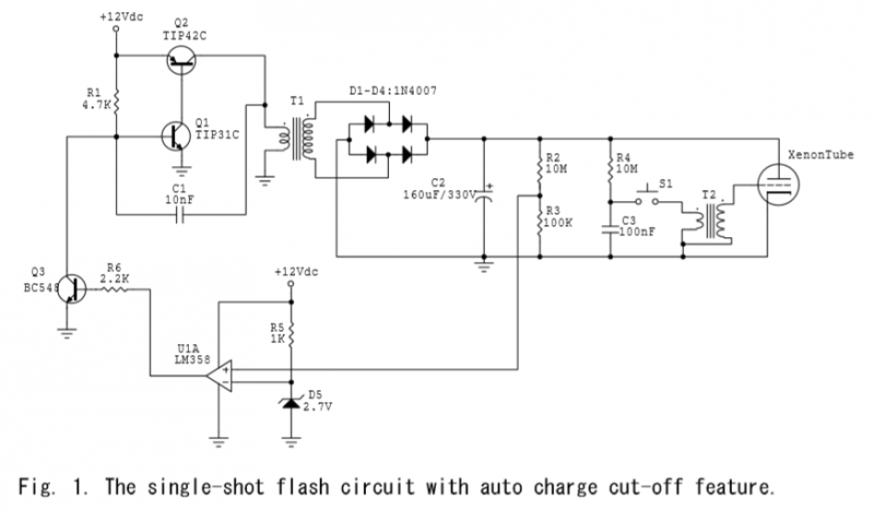
A voltage divider is created using resistors R2 (10MΩ) and R3 (100KΩ), which effectively reduces the voltage across capacitor C2 by a factor of approximately 100. The ground of C2 is connected to the inverter ground for reference. An...