
5 Zone Alarm Circuit

The described circuit operates as a security alarm system featuring multiple zones, each utilizing normally closed contacts. These contacts can be implemented using micro switches or standard alarm contacts, typically reed switches, which are known for their reliability in security applications. The system is designed with five zones: Zone 1 serves as a timed entry and exit point, necessitating a delay to allow authorized individuals to enter or exit without triggering the alarm. In contrast, Zones 2 through 5 are configured as immediate zones, designed to trigger the alarm instantaneously upon activation.
For the purpose of ensuring reliable operation over extended wiring distances, the circuit incorporates input capacitors (C1-C5) that provide RF immunity. This feature is critical in environments where electromagnetic interference might affect the performance of the alarm system. Additionally, components C7 and R14 are included to form a transient suppressor, which protects the circuit from voltage spikes that could occur due to switching transients or other electrical disturbances.
A key switch is integrated into the design to facilitate user interaction with the system, allowing for setting, unsetting, and resetting of the alarm. This switch plays a crucial role in the overall functionality, enabling users to manage the security state of the system effectively. The combination of these elements creates a robust alarm system capable of providing security across multiple zones while maintaining reliability and user-friendly operation.Each zone uses a normally closed contact. These can be micro switches or standard alarm contacts (usually reed switches). Zone 1 is a timed zone which must be used as the entry and exit point of the building. Zones 2 - 5 are immediate zones, which will trigger the alarm with no delay. Some RF immunity is provided for long wiring runs by the input capacitors, C1-C5. C7 and R14 also form a transient suppresser. The key switch acts as the Set/Unset and Reset switch. 🔗 External reference
Related Circuits
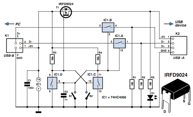
Individuals engaged in the experimentation or development of USB-connected peripheral hardware often find it frustrating to repeatedly disconnect and reconnect the plug to reestablish communication with the PC. This procedure is necessary, for instance, every time the peripheral device...
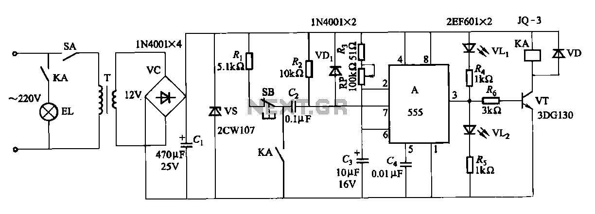
The second circuit for darkroom time exposure utilizes a 555 timer integrated circuit (IC A) for timing functions. A relay controlled by the circuit regulates the exposure light source. The exposure time can be adjusted using potentiometer RP, allowing...
A typical circuit for welding equipment is illustrated in the following circuit diagram. The turn-on delay can be accurately controlled with Potentiometer P2, allowing for effective discharge management. The welding equipment circuit typically incorporates several key components to ensure proper...
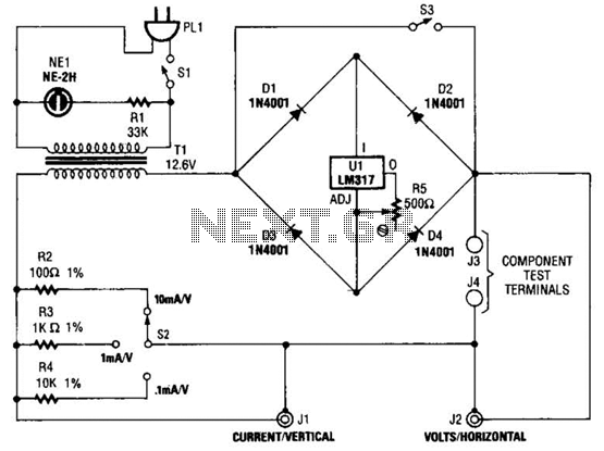
Useful for checking diodes, transistors, triacs, SCRs, resistors, and LEDs, this curve tracer should prove beneficial in the experimenter's lab. It displays the volt-ampere characteristic of a two-terminal device on an oscilloscope. This is a simple block diagram of...
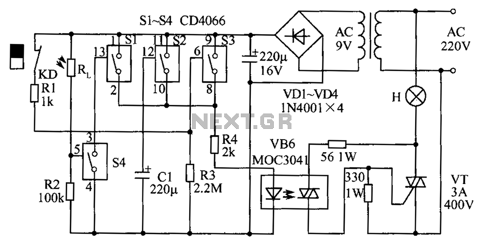
The circuit diagram illustrates a group of four analog electronic circuit switches (S1 to S4). Switches S1, S2, and S3 are utilized in a parallel delay circuit. When the power is activated, resistor R4 drives the triac VT, which...
The current feedback operational amplifier maintains a consistent bandwidth even when the open-loop gain is altered. This characteristic makes it particularly suitable for applications in video signal amplification and the driving circuits of video cables. The accompanying diagram illustrates...