
555 Based Simple Servo Controller

The circuit employs a 555 timer IC configured in astable mode to produce a continuous square wave output. The frequency of the output pulse is determined by the resistors and capacitor connected to the timer. In this design, the timing components are selected to achieve a pulse frequency of 50 Hz (20 ms period), which is suitable for controlling servos. The duty cycle, adjustable through the resistor values, allows for precise control of the servo position by varying the pulse width between 1 ms and 2 ms.
To achieve the desired duty cycle, two resistors (R1 and R2) and a timing capacitor (C1) are connected to the 555 timer. The values of R1 and R2 can be calculated using the formula for the astable mode of the 555 timer. The output from the timer is connected to the control signal input of the servos. When multiple servos are connected to the same output, they will respond identically to the control signal, making it possible to synchronize their movements.
When designing the power supply for this circuit, it is crucial to consider the current requirements of the servos. Servos typically draw a significant amount of current, especially under load, which can range from hundreds of milliamps to several amps. Therefore, a power supply capable of delivering sufficient current is necessary to ensure reliable operation. It is advisable to use a power supply with a current rating that exceeds the total current draw of all connected servos to prevent voltage drops and ensure consistent performance.
In summary, this circuit provides a simple yet effective means of controlling multiple servos using a 555 timer IC, with careful attention needed for power supply design to accommodate the high current demands of the servos during operation.The circuit is pretty self explanatory. We use a 555 timer IC to generate a pulse every 20ms with a duty cycle of between 5 and 10% (1-2ms). All the parts used are common components. You can drive multiple servos with the same signal using this circuit to all have the same output or build multiple driver circuits to command many servos to differen t outputs. Also note that servos require alot of current when commanding them and also to hold a position under load, this can be up to a few amps! So make note of this when designing your power supply. 🔗 External reference
Related Circuits
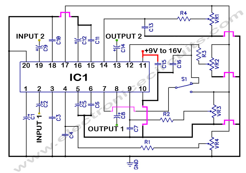
LM1036 Stereo Tone (Bass, Treble, Volume, Loudness, Balance) Controller Circuit. The LM1036 is a DC controlled tone (bass/treble), volume, and loudness controller designed for audio applications. The LM1036 circuit serves as an integrated solution for controlling various aspects of audio...
A stepper motor is an effective solution for achieving high-precision motion control. To operate a stepper motor, a corresponding control circuit is required. A stepper motor control circuit typically consists of several key components that facilitate the precise movement of...
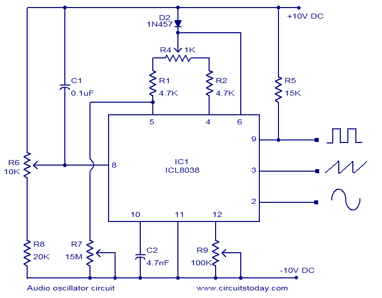
ICL8038-based audio oscillator circuit. Simultaneous sine, triangle, and square waveforms. Dual supply operation. Covers the full audio frequency range. The ICL8038 is a precision waveform generator integrated circuit that can produce sine, triangle, and square waveforms simultaneously. This versatility makes...
You need a power supply for a project, but only have a DC adapter available, so you can't use my AC power adapter trick (Project 05). This little project came about because a reader had just this problem, and...
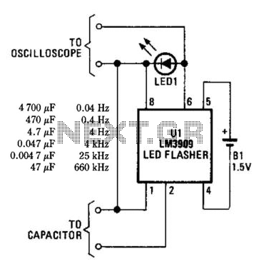
An LM3909 LED flasher functions as an oscillator, with the frequency determined by the capacitor connected to its terminals. The LED can be utilized to visually count frequency using a stopwatch for large capacitors (C > 500µF). The LM3909 is...
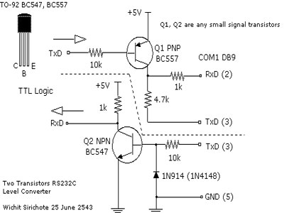
To connect a microcontroller project to the COM port of a PC, an RS-232 converter is required. Various chips are available to address this need, such as the MAX232 and DS275. The RS-232 standard is widely used for serial communication...