
Simple RS 232 Level Converter

The RS-232 standard is widely used for serial communication between devices, including microcontrollers and computers. The voltage levels of RS-232 signals are typically between -15V and +15V, which are incompatible with the TTL (Transistor-Transistor Logic) levels of most microcontrollers, typically ranging from 0V to 5V or 0V to 3.3V. Therefore, an RS-232 converter is essential for level shifting and ensuring proper communication.
The MAX232 is a popular choice for this application. It contains dual voltage level translators that convert TTL logic levels to RS-232 levels and vice versa. The device usually requires a dual power supply of +5V for the TTL side and a -10V to -15V supply for the RS-232 side, which can be generated using external capacitors and charge pumps integrated within the chip.
The DS275 is another option that functions similarly to the MAX232, providing a bidirectional level translation. It is designed to operate at lower power levels, making it suitable for battery-operated devices. The DS275 also includes features such as built-in protection against over-voltage and short-circuit conditions.
In designing a circuit with either of these chips, it is crucial to connect the microcontroller’s TX (transmit) pin to the RX (receive) pin of the RS-232 converter and the RX pin of the microcontroller to the TX pin of the converter. Additionally, proper decoupling capacitors should be placed close to the power supply pins of the chips to ensure stable operation.
Overall, incorporating an RS-232 converter like the MAX232 or DS275 into a microcontroller project facilitates reliable communication with a PC's COM port, enabling data exchange for various applications.When you need connect your Microcontroller Project to COM port in PC you need RS 232 converter. There are many chip to solve the problem like MAX232, DS275 etc.. 🔗 External reference
Related Circuits
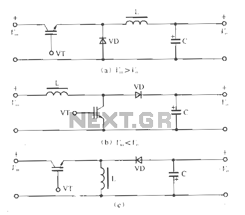
The circuit operates without isolation for both input and output voltage, utilizing a working switch along with an inductor (L), diode (D), and capacitor (C) to form a basic inverter circuit. There are three types of converters: the step-down...
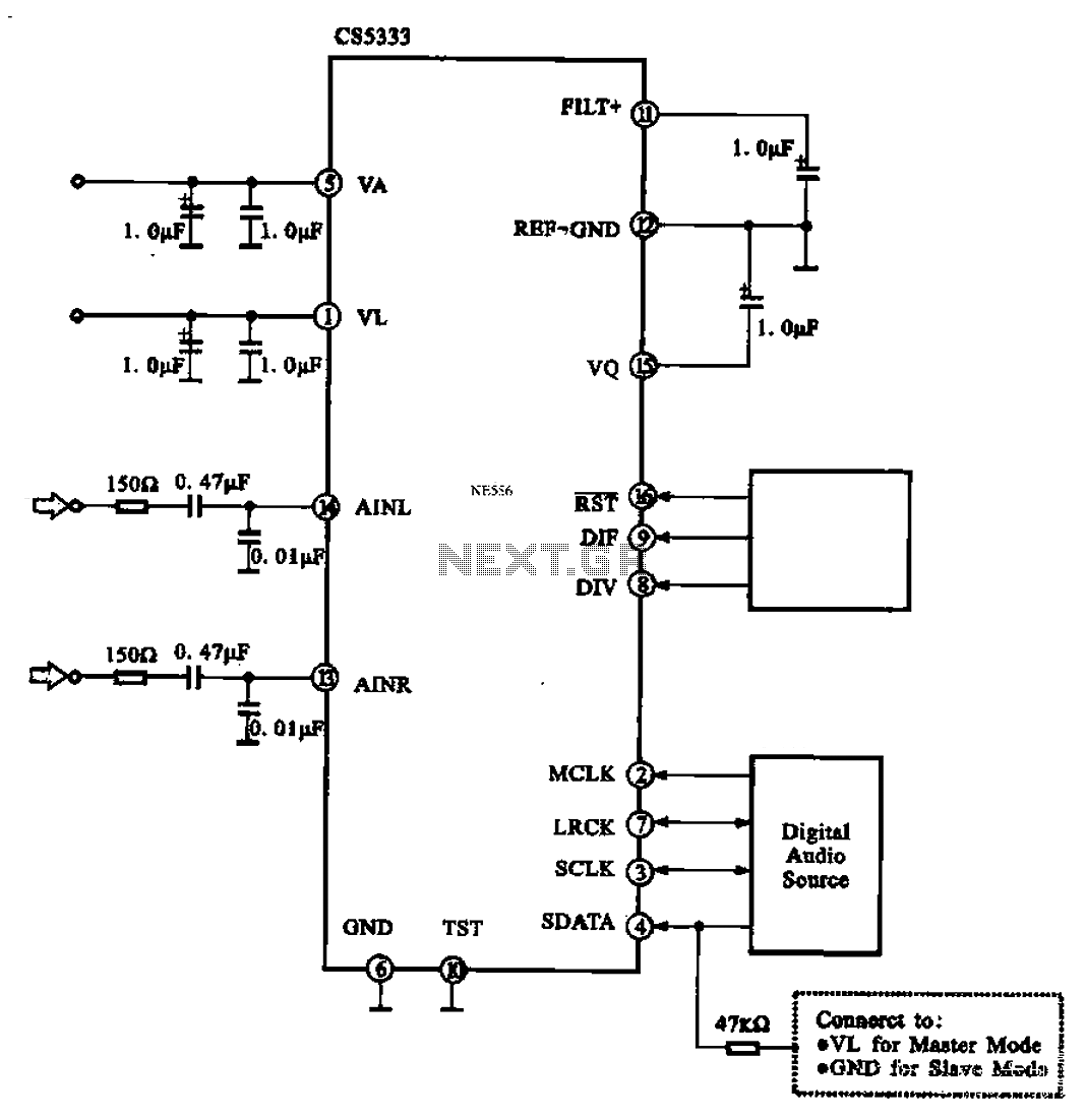
Audio A/D converter circuit configuration using the CS5333 chip, which is a high-performance 24-bit, 96 kHz stereo A/D converter commonly used in digital products. This circuit converts one or more audio signals into a digital signal for processing and...
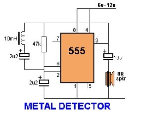
Assemble the circuit on a perfboard or PCB, excluding the inductor. Attach two long wires in place of the inductor. Use a long rod and position the inductor. The circuit assembly begins with the preparation of a perfboard or printed circuit...
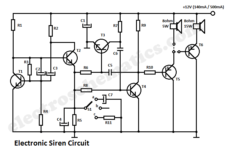
This circuit generates a tone that resembles a siren. The generator section consists of a combination of PNP and NPN transistors that form a free-running multivibrator. If capacitor C2 were connected to the positive line of the power supply,...
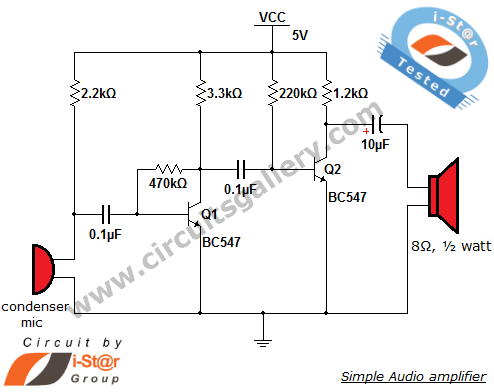
This circuit diagram is a simple and effective design for amplifying weak signals from a capacitive condenser microphone. It is suitable for sound sensing applications and various automatic robotic sensors. While a more complex audio amplifier circuit using the...
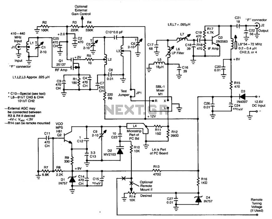
Ll, Ql, L2, and L3 form an RF amplifier stage that feeds Ml, a doubly balanced mixer. Q4 is a local oscillator stage operating in the 375-MHz range. Signals in the 420- to 450-MHz range from Ql are mixed...